
Air film cooling platelet injector

A film cooling and injector technology, which is used in jet propulsion devices, machines/engines, rocket engine devices, etc., can solve problems such as easy failure and short combustion distance, and achieve positioning and size requirements, and layer thickness. Small, good compatibility

Inactive Publication Date: 2018-07-31
NAT UNIV OF DEFENSE TECH
View PDF4 Cites 1 Cited by
  • Summary
  • Abstract
  • Description
  • Claims
  • Application Information

AI Technical Summary

Problems solved by technology

Compared with ordinary injectors, the combustion distance of laminate injectors is shorter, and the injection panel is more affected by heat and mechanical loads, and is prone to failure

Method used


Image

  • Air film cooling platelet injector
  • Air film cooling platelet injector
  • Air film cooling platelet injector

Examples


Embodiment Construction

[0045] The present invention will be described in detail below with reference to the accompanying drawings and examples. It should be noted that, in the case of no conflict, the embodiments of the present invention and the features in the embodiments can be combined with each other. For the convenience of description, if the words "up", "down", "left" and "right" appear in the following, it only means that the directions of up, down, left and right are consistent with the drawings themselves, and do not limit the structure.

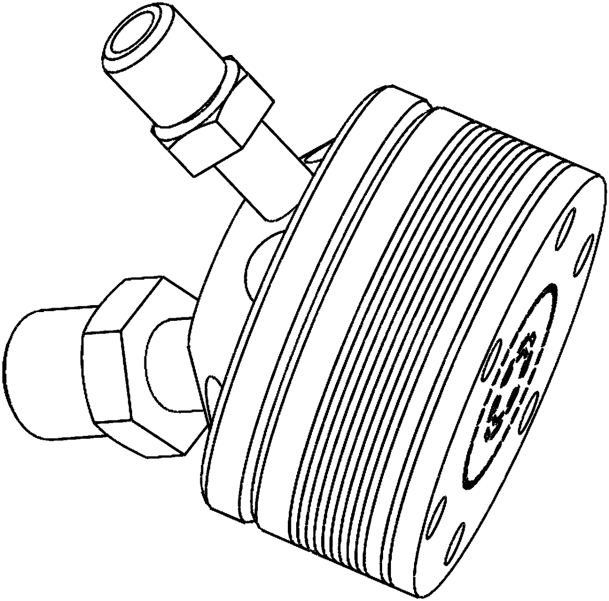
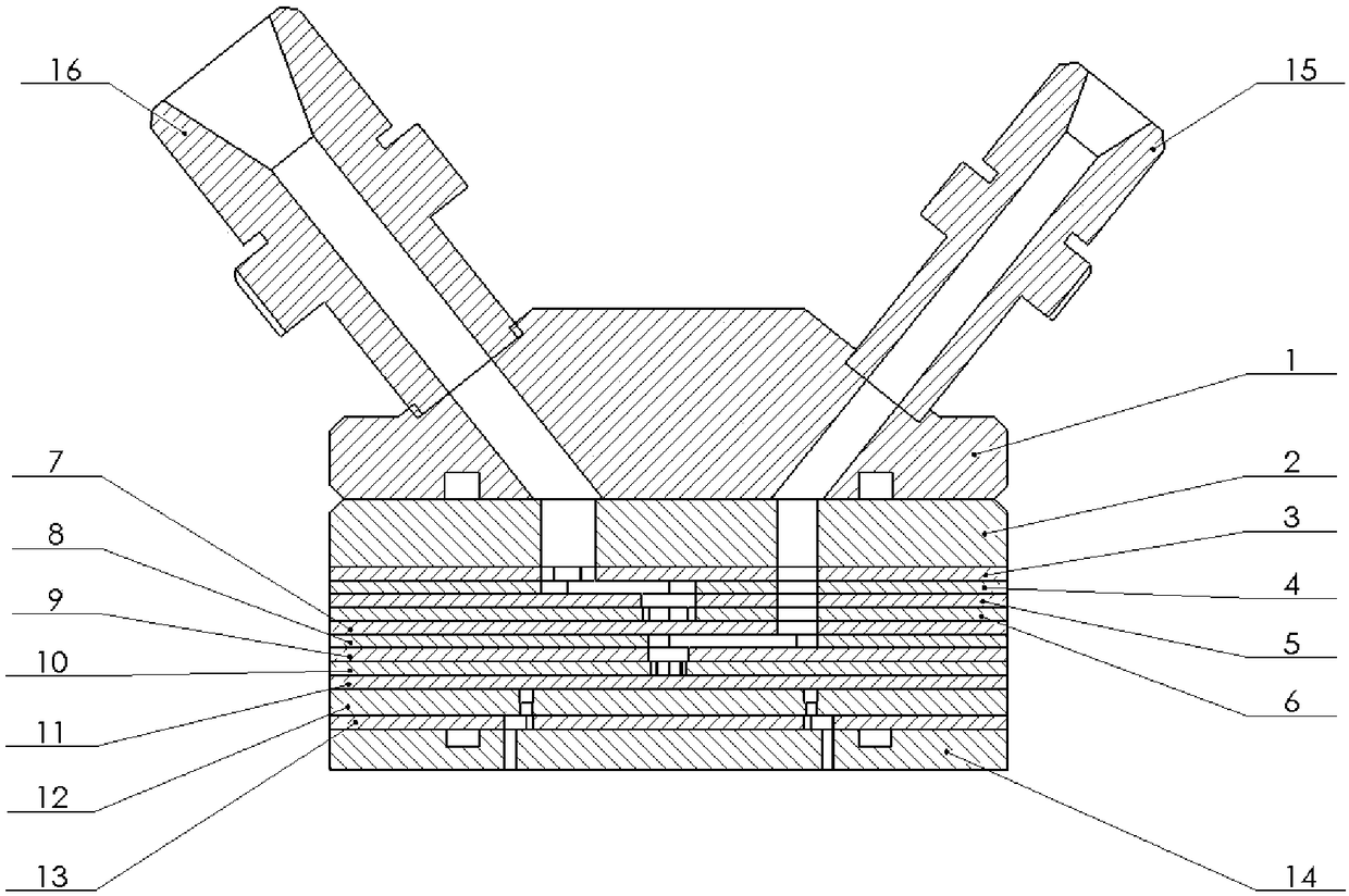
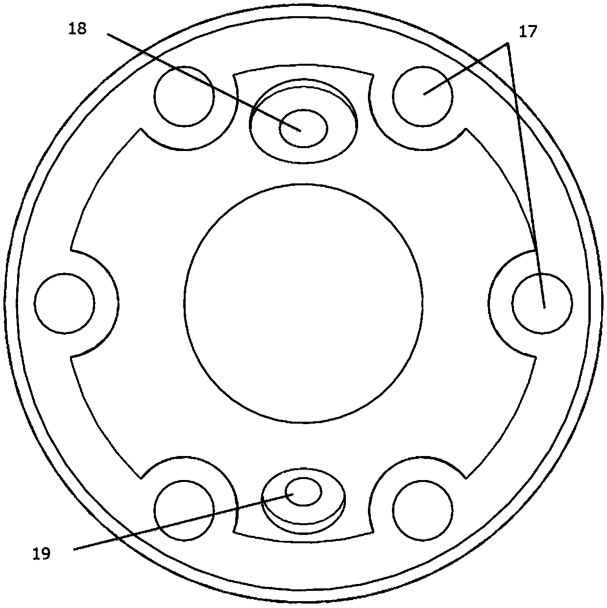
[0046] Such as Figure 1 to Figure 16 As shown, a film cooling laminate injector includes an injector body, and the injector body includes a third manifold 5, a fourth manifold 6, a fifth manifold 7, and a sixth manifold stacked in sequence. Splitter plate 8, seventh splitter plate 9, eighth splitter plate 10, and ninth splitter plate 11, the third splitter plate 5 is provided with a third through hole A30 communicating with the fuel supply source, and a...


PUM


Abstract

The invention relates to an air film cooling platelet injector. The air film cooling platelet injector comprises an injector body, wherein a fuel flow channel which communicates with a fuel supply source and an oxidant flow channel which communicates with an oxidant supply source are formed in the injector body; the fuel flow channel comprises a fuel inlet channel, a radial fuel shunting chamber and a plurality of fuel shunting channels which communicate with each other in sequence, and the plurality of fuel shunting channels are circumferentially distributed along the central axis of the fuelshunting chamber; and the oxidant flow channel comprises an oxidant inlet channel, an oxidant turning cavity, a radial oxidant shunting chamber and a plurality of oxidant shunting channels which communicate with each other in sequence, the central axis of the fuel shunting chamber coincides with that of the oxidant shunting chamber, and the plurality of oxidant shunting channels are circumferentially distributed along the central axis of the oxidant shunting chamber. According to the air film cooling platelet injector, a combustion chamber body and an injector panel are cooled by adopting anair film cooling method, so that the service life of the injector and an engine can be prolonged.

Description

technical field [0001] The invention belongs to the technical field of liquid rocket engine propulsion, and relates to an injector device used on a small-thrust attitude control engine, in particular to a layered injector using head gas film cooling. Background technique [0002] In a liquid rocket engine, the injector plays a decisive role in propellant atomization, mixing, combustion and stability. Traditional injectors generally adopt a three-bottom, two-chamber structure. The fuel and oxidant have their own liquid collecting chambers. The liquid collecting chamber volume will reduce the stability of small thrust engines, making the response characteristics worse, pulse performance and specific impulse decrease, and even Can produce exhaust plume pollution and cause damage to spacecraft or satellite hardware. The laminate injector is a new type of liquid rocket engine injector developed by the American Aerojet company in the 1970s. Compared with the traditional injector,...

Claims


Application Information

Patent Timeline
IPC IPC(8): F02K9/52
CPCF02K9/52
Inventor 尹亮刘伟强沈斌贤刘洪鹏李开张家奇陈海安通姚霄牟万辉
Owner NAT UNIV OF DEFENSE TECH
Learn More