Material barrel special machine

A technology of material barrel and special machine, applied in the field of special machine of material barrel, can solve the problems such as the height of the gun body is difficult to compress, the nozzle is difficult to remove, and the small inner hole is not suitable, and the effect of reducing the processing process, simple structure and improving the cooling effect is achieved.

Inactive Publication Date: 2018-07-31
宁波驰迈激光科技有限公司
View PDF1 Cites 2 Cited by
  • Summary
  • Abstract
  • Description
  • Claims
  • Application Information

AI Technical Summary

Problems solved by technology

[0003] At present, the mainstream plasma powder surfacing guns are mostly assembled welding guns fastened by screws. In order to make the upper and lower gun bodies non-conductive, the fastening screws must be insulated, which will inevitably increase the volume of the welding gun, and the height of the gun body is difficult to compress , so this type of gun is not suitable for surfacing welding of small inner holes
Also someone has carried out the design of the welding torch with small inner hole, such as the small inner hole welding torch disclosed by the utility model whose authorization announcement number is CN 203484793U.
In addition, this gun has two fatal flaws: 1. There is no cooling inside the nozzle, and the high temperature can easily burn out the nozzle; 2. The nozzle and the lower gun body are connected by threads. work efficiency
At present, there is no inner hole gun that can meet the above requirements on the market
And the current mainstream powder feeders for plasma powder surfacing are mostly single-tube powder feeders. The biggest defect of this type of powder feeder is that the equipment must be stopped after the alloy powder used for welding is used up each time. The powder feeder can only work normally after adding powder, which greatly affects the work efficiency

Method used


Image

  • Material barrel special machine
  • Material barrel special machine
  • Material barrel special machine

Examples


Embodiment Construction

[0026] The specific embodiments of the present invention will be further described below with reference to the accompanying drawings. It should be noted here that the descriptions of these embodiments are used to help the understanding of the present invention, but do not constitute a limitation of the present invention. In addition, the technical features involved in the various embodiments of the present invention described below can be combined with each other as long as they do not conflict with each other.

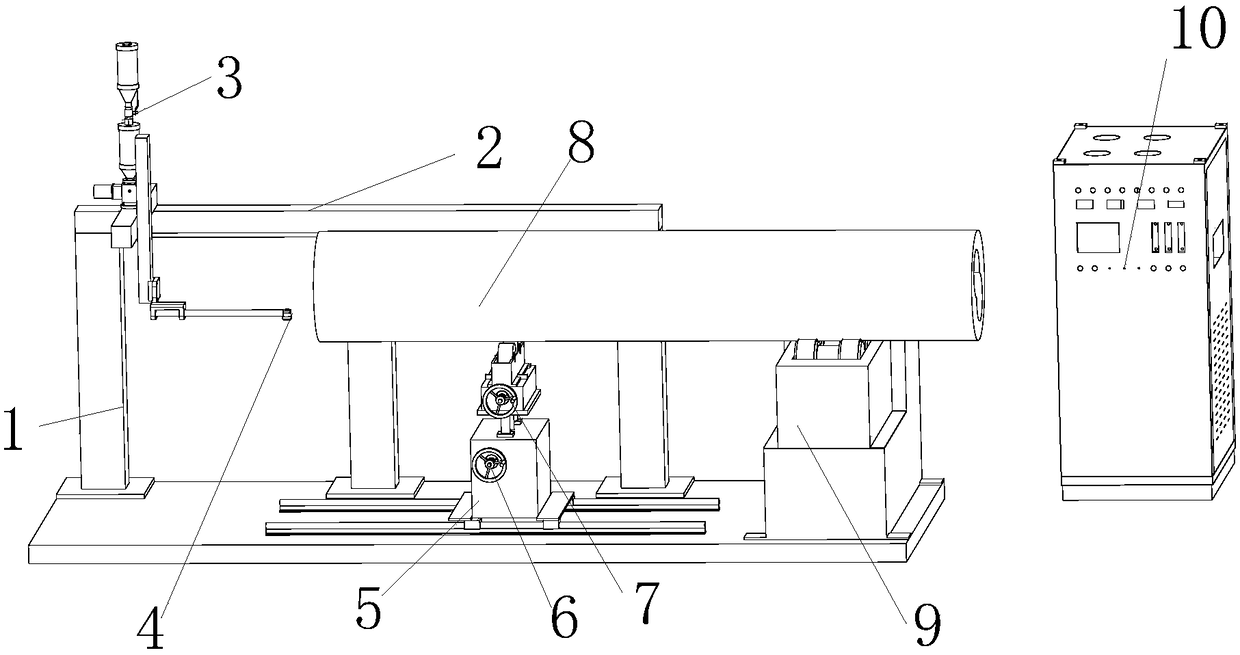
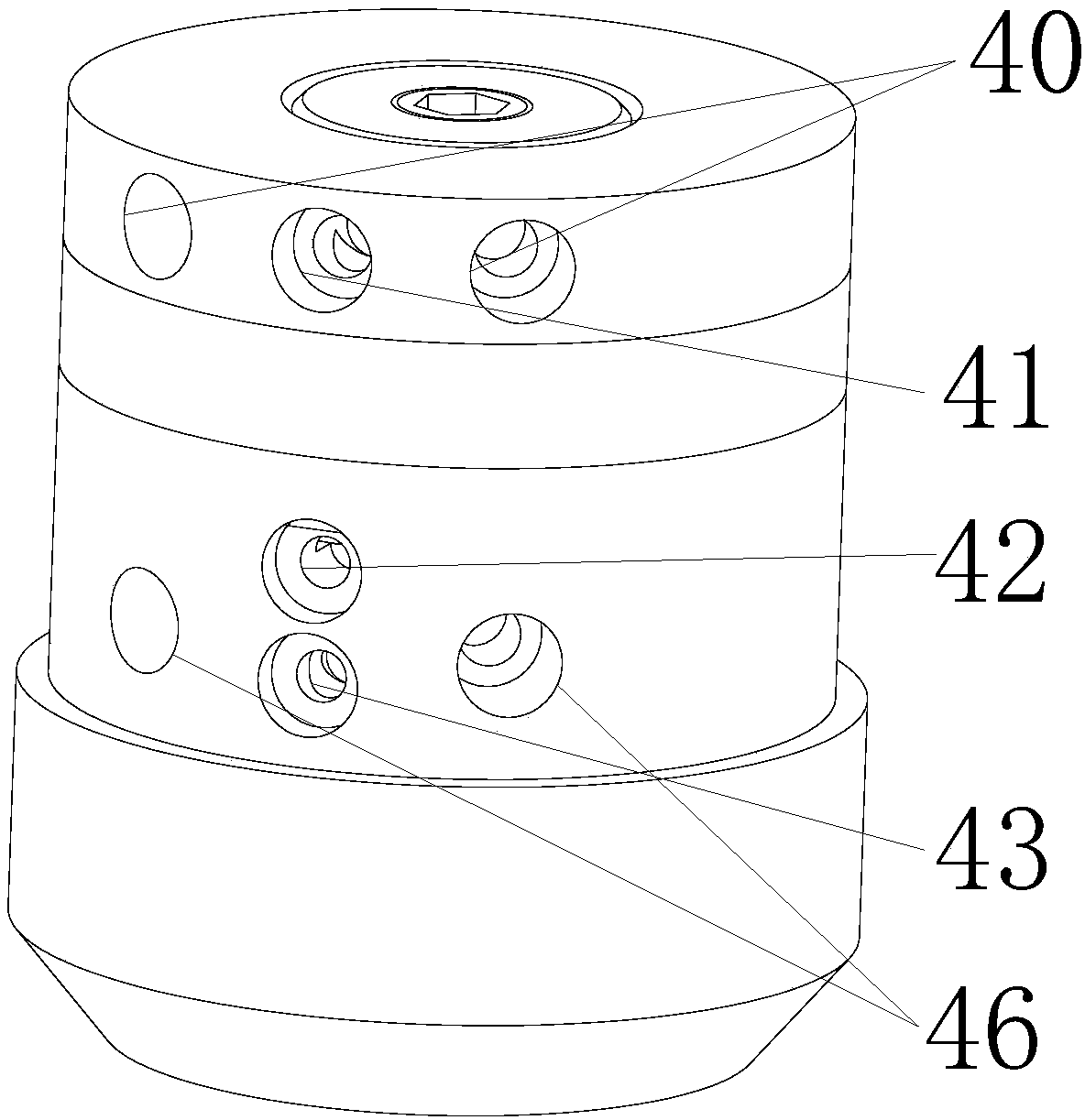
[0027] refer to figure 1 , figure 2 , image 3 and Figure 4 Shown is a schematic structural diagram of a barrel machine, a schematic structural diagram of a plasma surfacing torch, a perspective view of a plasma surfacing torch, and a schematic structural diagram of a powder channel. A barrel machine, comprising a module bracket 1, a module 2 connected to the module bracket 1, a plasma surfacing gun 4 that can be adjusted and installed on the module 2, and a pla...


PUM


Abstract

The invention belongs to the technical field of material barrel special machines and particularly relates to a material barrel special machine. The material barrel special machine comprises a module support, a module connected with the module support, a plasma surfacing gun adjustably mounted on the module, a continuous powder feeder arranged at the upper end of the plasma surfacing gun for connection, a driving mechanism, a driven mechanism, a material barrel which is adjusted through the driving mechanism and the driven mechanism, and a plasma control power source which controls the plasma surfacing gun and the continuous powder feeder. The plasma surfacing gun comprises an upper gun body, an insulator, a lower gun body and a spray nozzle which are connected in sequence from top to bottom, wherein the insulator is connected with the upper gun body and the lower gun body through screw threads, and a protective cover is disposed on the outer side of the spray nozzle. The material barrel special machine disclosed by the invention is compact in structure, capable of achieving continuous feeding of powder and improving production efficiency, good in water path circulating cooling effect and long in working time.

Description

technical field [0001] The invention relates to a special bucket machine. It belongs to the technical field of special tank machines. Background technique [0002] The existing surface strengthening of the barrel is to improve the wear resistance and corrosion resistance of the surface of the part by cladding a layer of alloy powder with special properties on the surface of the part, thereby prolonging its service life. This technology has the advantages of high temperature, low dilution rate and good controllability, and is widely used in aerospace, ships, valves, mining machinery, screw and other industries. [0003] At present, the mainstream plasma powder surfacing guns are mostly assembled welding guns fastened by screws. In order to make the upper and lower gun bodies non-conductive, the fastening screws must be insulated, which will inevitably increase the volume of the welding gun, and the height of the gun body is difficult to compress , so this type of gun is not...

Claims


Application Information

Patent Timeline
Patent Type & Authority Applications(China)
IPC IPC(8): B23K10/02
CPCB23K10/027
Inventor 鲍方明
Owner 宁波驰迈激光科技有限公司
Why Eureka
Try Eureka