Eureka AIR delivers breakthrough ideas for toughest innovation challenges, trusted by R&D personnel around the world.

Powder for laser cladding in-situ self-generated vanadium carbide reinforced iron-based alloy and preparation method

An in-situ self-generated and laser cladding technology, which is applied in the coating process and coating of metal materials, can solve the problem that it is difficult to control the sufficient and uniform mixing of the reinforcement phase particles and the coating powder, and the poor combination of the reinforcement phase particles and the matrix interface , It is impossible to guarantee that the reinforcement phase particles will not be polluted, etc., to achieve the effect of strong bonding strength, low price, and enhanced wettability

Active Publication Date: 2018-07-31
SHENYANG POLYTECHNIC UNIV
View PDF3 Cites 5 Cited by
  • Summary
  • Abstract
  • Description
  • Claims
  • Application Information

AI Technical Summary

Problems solved by technology

Although adding reinforcement phase particles directly to the coating has the advantages of simplicity and convenience, and controllable reinforcement phase content, there are also some unavoidable disadvantages: first, it cannot be guaranteed that the reinforcement phase particles will not Contaminated, it is easy to introduce impurities into the coating, resulting in poor bonding between the reinforcing phase particles and the matrix, and even easily causing interface cracks, failing to achieve the expected strengthening effect; secondly, it is difficult to control the reinforcing phase particles and the coating The powder is fully and evenly mixed, which is mainly caused by the difference in powder particle size and powder density, which will cause uneven distribution of reinforcement phase particles in the coating, and the strengthening effect will be greatly reduced

Method used


Image

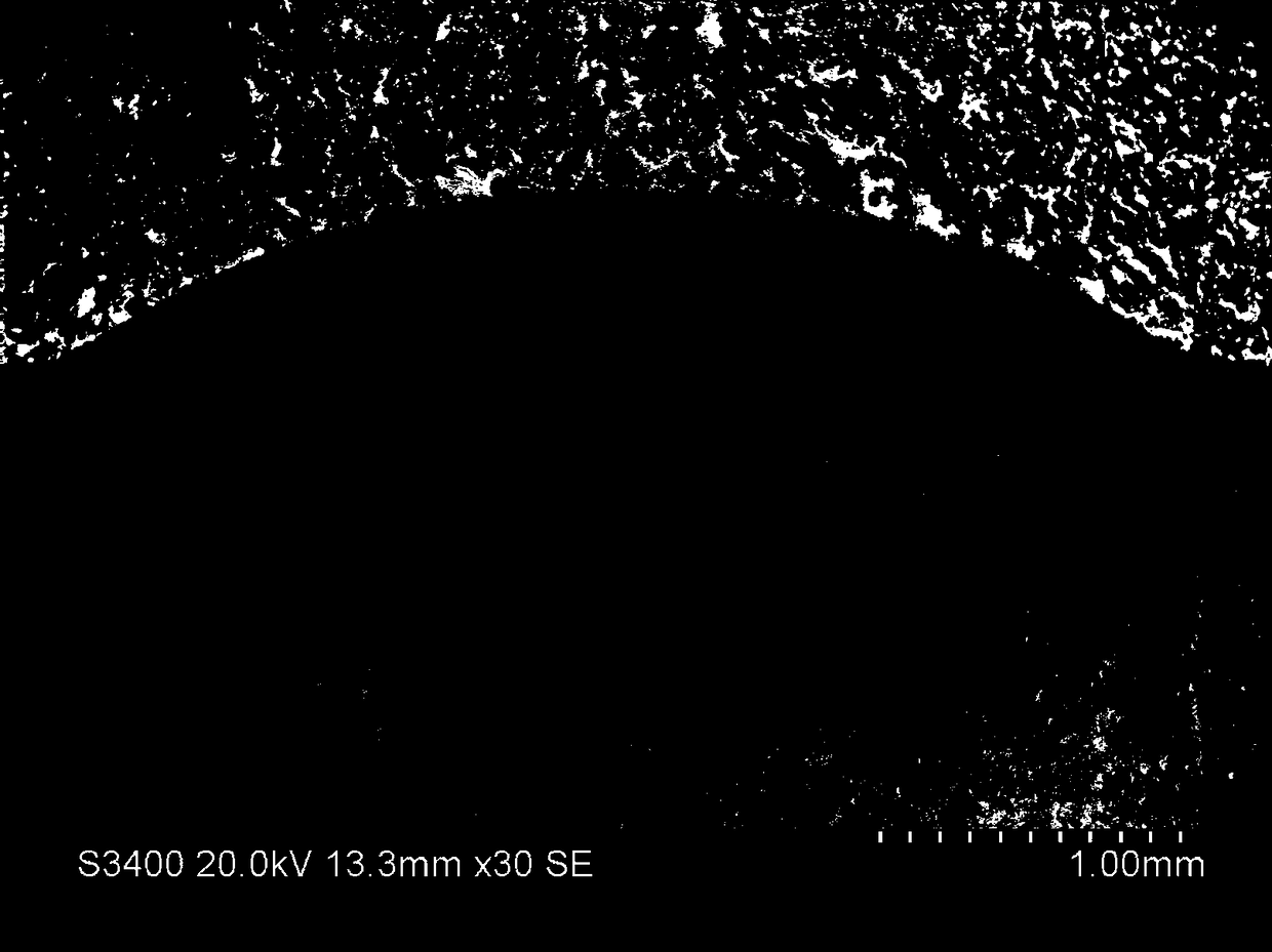
  • Powder for laser cladding in-situ self-generated vanadium carbide reinforced iron-based alloy and preparation method
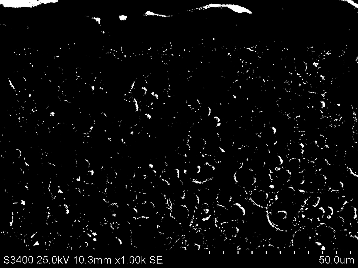
  • Powder for laser cladding in-situ self-generated vanadium carbide reinforced iron-based alloy and preparation method
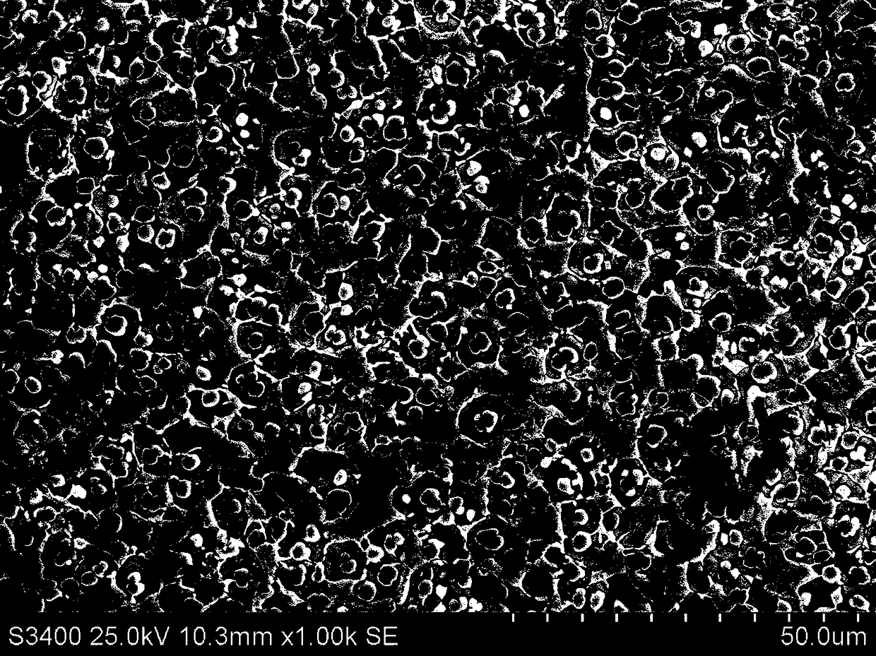
  • Powder for laser cladding in-situ self-generated vanadium carbide reinforced iron-based alloy and preparation method

Examples


Embodiment 1

[0045] Using alloy powder I to prepare V on the surface of low carbon alloy steel substrate 8 C 7 Particle-reinforced iron-based alloy laser cladding layer.

[0046] The composition (mass fraction) is C 4.00%, V 16.00%, Cr 8.00%, Si 0.90%, Mo 1.00%, Mn0.90%, Ni 0.40%, Al 0.30%, the total mass fraction of P and S≤0.03% , O≤300ppm, and the rest is Fe. The alloy powder I was dried in a vacuum oven at 120°C for 2 to 5 hours, and then the laser cladding test was carried out. Using CO 2 The laser is used for laser cladding, the laser beam wavelength is 10.64μm, the laser power is 4.0kW, the scanning speed is 400mm / min~700mm / min, and the overlapping rate of multi-pass laser cladding is 50% for large area processing. The speed of the powder feeder in the synchronous powder feeding method is 600r / min, the purity of the shielding gas Ar is 99.95%, and the speed of the shielding gas is 10-20L / min. The thickness of the obtained laser cladding layer is 0.6-0.9 mm.

Embodiment 2

[0048] Prepare V on the surface of low carbon alloy steel substrate by using alloy powder II 8 C 7 Particle-reinforced iron-based alloy laser cladding layer.

[0049] The composition (mass fraction) is C 4.20%, V 17.00%, Cr 9.00%, Si 1.10%, Mo 1.50%, Mn1.10%, Ni 0.50%, Al 0.40%, the total mass fraction of P and S≤0.03% , O ≤ 300ppm, and the rest is Fe alloy powder II to be clad in a vacuum oven, dried at 120 ° C for 2 to 5 hours, and then the laser cladding test. Using CO 2 The laser is used for laser cladding test, the laser wavelength is 10.64μm, the laser power is 4.0kW, the scanning speed is 400mm / min~700mm / min, and the overlapping rate of multi-pass cladding is 50%. The speed of the powder feeder in the synchronous powder feeding method is 600r / min, the purity of the shielding gas Ar is 99.95%, and the speed of the shielding gas is 10-20L / min. The thickness of the obtained laser cladding layer is 0.6-0.9 mm.

Embodiment 3

[0051] Prepare V on the surface of low carbon alloy steel substrate by using alloy powder III 8 C 7 Particle-reinforced phase iron-based alloy laser cladding layer.

[0052] The composition (mass fraction) is C 4.40%, V 18.00%, Cr 10.00%, Si 1.30%, Mo 2.00%, Mn 1.20%, Ni 0.70%, Al 0.50%, the total mass fraction of P and S≤0.03%% , O ≤ 300ppm, and the rest is Fe alloy powder III to be clad in a vacuum oven at 120 ℃ for 2 to 5 hours, and then conduct a laser cladding test. Using CO 2 The laser is used for laser cladding, the laser beam wavelength is 10.64 μm, the laser power is 4.0kW, the scanning speed is 400mm / min~700mm / min, and the overlapping rate of multiple passes of large-area cladding is 50%. The speed of the powder feeder in the synchronous powder feeding method is 600r / min, the purity of the shielding gas Ar is 99.95%, and the speed of the shielding gas is 10-20L / min. The thickness of the obtained laser cladding layer is 0.6-0.9 mm.


PUM

PropertyMeasurementUnit
Thicknessaaaaaaaaaa
Hardness valueaaaaaaaaaa
Hardnessaaaaaaaaaa

Abstract

The invention discloses powder for laser cladding in-situ self-generated vanadium carbide reinforced iron-based alloy and a preparation method. The alloy powder prepared by a vacuum gas atomization method comprises, by mass, 4.00%-4.40% of C, 16.00%-18.00% of V, 8.00%-10.00% of Cr, 0.90%-1.30% of Si, 1.00%-2.00% of Mo, 0.90%-1.20% of Mn, 0.40%-0.70% of Ni, 0.30%-0.50% of Al, P, S, less than or equal to 300 ppm of O, and the balance Fe, wherein the total mass fraction of P and S is less than or equal to 0.03%. The preparation method comprises the steps that the alloy powder clads the surface oflow-carbon alloy steel base material through laser by adopting a CO2 laser processing system in a synchronous powder feeding mode, the cladding-layer powder absorbs laser energy to form a molten poolon the surface of the base material, a C element and a V element in the molten pool react to generate an in-situ self-generated V8C7 ceramic reinforced phase, and meanwhile, the cladding layer and the base material form good metallurgical bonding. By preparing the in-situ self-generated V8C7 particle reinforced iron-based alloy laser cladding layer, the hardness and the wear resistance of the surface of a low-alloy steel component can be remarkably improved, and the method can be widely applied to laser manufacturing and remanufacturing of mechanical parts under friction and wear working conditions in the industrial field, and has remarkable economic and social benefits.

Description

technical field [0001] The invention relates to the field of preparation of new surface engineering materials, in particular to a laser cladding in-situ self-generated vanadium carbide reinforced iron-based alloy powder and a preparation method. Background technique [0002] On a global scale, iron ore underground resources are very rich, and the reserves of iron element are second only to oxygen, silicon and aluminum elements, ranking fourth. Because of its low price, it is widely used in mechanical parts and daily life in various fields of industry, agriculture and the pillar industries of the national economy. However, most iron-based alloys or iron products have low hardness and poor wear resistance. In order to adapt to the continuous development of society With the gradual improvement of material performance requirements, especially under the conditions of friction and wear of mechanical equipment, one way is to find more wear-resistant materials, which also means chal...

Claims


Application Information

Patent Timeline
IPC IPC(8): B22F1/00B22F9/08C22C37/10C22C37/08C23C24/10
CPCB22F1/0003B22F9/082C22C37/08C22C37/10C23C24/103
Inventor 张春华王冲韩雨柔徐韵华崔雪张瀚方张松
Owner SHENYANG POLYTECHNIC UNIV
Why Eureka
Eureka Blog
Learn More