
High-snow-slide-tolerance deep-groove power device

A technology of avalanche tolerance and power devices, applied in semiconductor devices, electrical components, circuits, etc., can solve the problems of reducing device breakdown voltage and device withstand voltage, reducing peak current density, low on-resistance, and improving avalanche The effect of endurance

Pending Publication Date: 2018-07-27
WUXI NCE POWER
View PDF0 Cites 5 Cited by
  • Summary
  • Abstract
  • Description
  • Claims
  • Application Information

AI Technical Summary

Problems solved by technology

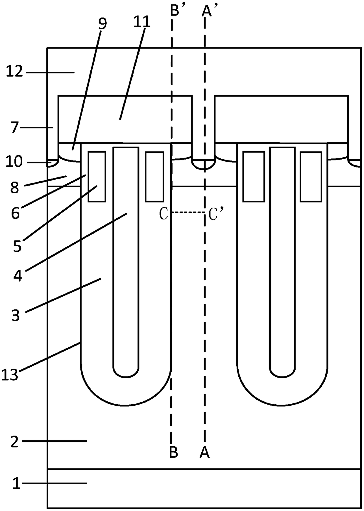
[0003] like figure 1 Shown is a schematic cross-sectional structure diagram of a traditional deep trench power device. In order to further reduce the on-resistance of the deep trench MOSFET, an epitaxial layer with a lower resistivity is often used, but this will reduce the breakdown voltage of the device. In order to make If the breakdown voltage does not decrease, a thicker field oxygen layer 3 must be used. However, during the UIS test, too thick a field oxygen layer 3 will cause the current to converge to the single via hole 7 in the center of the platform between the trenches 13, resulting in The local current concentration of the device reduces the local withstand voltage of the device, resulting in the formation of breakdown weak points

Method used


Image

  • High-snow-slide-tolerance deep-groove power device
  • High-snow-slide-tolerance deep-groove power device
  • High-snow-slide-tolerance deep-groove power device

Examples


Embodiment Construction

[0020] The present invention will be further described below in conjunction with specific drawings and embodiments.

[0021] The present invention is not limited to the following embodiments, and the figures referred to in the following descriptions are set up for the purpose of understanding the content of the present invention, that is, the present invention is not limited to the device structures illustrated in the figures, and is applicable to IGBT devices , which is also applicable to MOSFET devices.

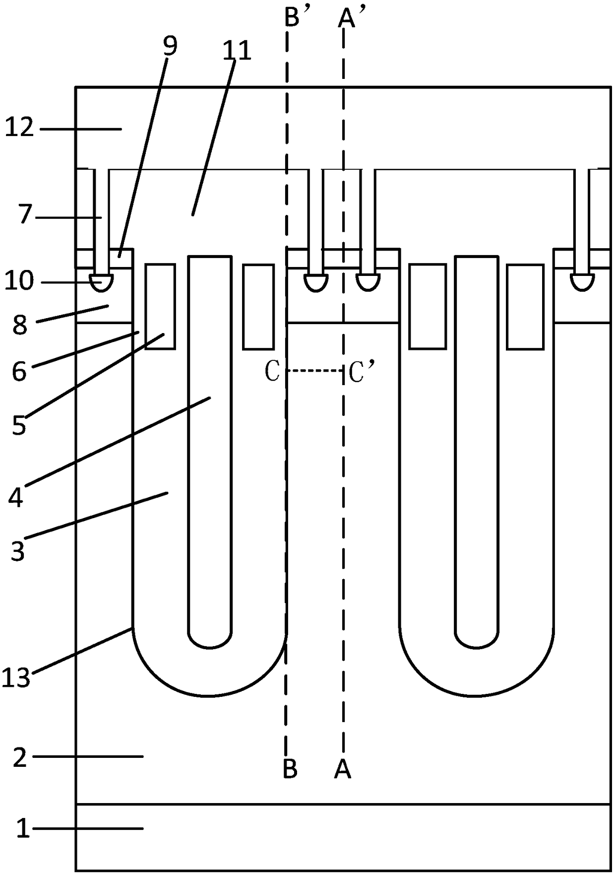
[0022] Such as figure 2 As shown, Embodiment 1 takes a MOSFET device, and the first conductivity type is N-type, and the second conductivity type is P-type as an example, a deep trench 13 power device with high avalanche resistance, including N for drawing out the drain region type silicon substrate 1 and an N-type silicon epitaxial layer 2 located on the N-type silicon substrate 1, a groove 13 is provided in the N-type silicon epitaxial layer 2, and a field is arranged i...


PUM


Abstract

The invention belongs to the technical field of manufacturing of semiconductor devices and relates to a high-snow-slide-tolerance deep-groove power device. The device comprises a first electric-condition-type silicon substrate and a first electric-condition-type silicon epitaxial layer, grooves are formed in the first electric-condition-type silicon epitaxial layer, and field oxygen layers, shieldgrids, grid electrodes and grid oxygen layers are arranged in the grooves; second electric-condition-type body areas and first electric-condition-type source areas are arranged between the adjacent grooves, and insulation dielectric layers and source electrode metal are arranged in the grooves and the first electric-condition-type source areas. The device is characterized in that in a platform area between the adjacent grooves, the source electrode metal is in contact with the second electric-condition-type body areas through two through holes, and second electric-condition-type source areasare arranged below all the through holes; a traditional single through hole is improved into double through holes, current can be effectively inhibited from being gathered to the center of a platform,the generation of weak point breakdown is inhibited accordingly, the epitaxial layer with lower specific resistance and the thicker field oxygen layers can be adopted for the deep-groove device, andthen the conduction resistance of the device is lowered.

Description

technical field [0001] The invention relates to a deep trench power device, in particular to a deep trench power device with high avalanche tolerance, and belongs to the technical field of manufacturing semiconductor devices. Background technique [0002] In the field of power semiconductor devices, deep trench MOSFETs can significantly increase channel density and reduce characteristic on-resistance. Therefore, deep trench MOSFETs have been widely used. [0003] Such as figure 1 Shown is a schematic cross-sectional structure diagram of a traditional deep trench power device. In order to further reduce the on-resistance of the deep trench MOSFET, an epitaxial layer with a lower resistivity is often used, but this will reduce the breakdown voltage of the device. In order to make If the breakdown voltage does not decrease, a thicker field oxygen layer 3 must be used. However, during the UIS test, too thick a field oxygen layer 3 will cause the current to converge to the singl...

Claims


Application Information

Patent Timeline
Patent Type & Authority Applications(China)
IPC IPC(8): H01L29/739H01L29/78H01L29/417H01L29/423
CPCH01L29/41741H01L29/41766H01L29/4236H01L29/7397H01L29/7827H01L29/7831
Inventor 朱袁正周锦程
Owner WUXI NCE POWER
Learn More