
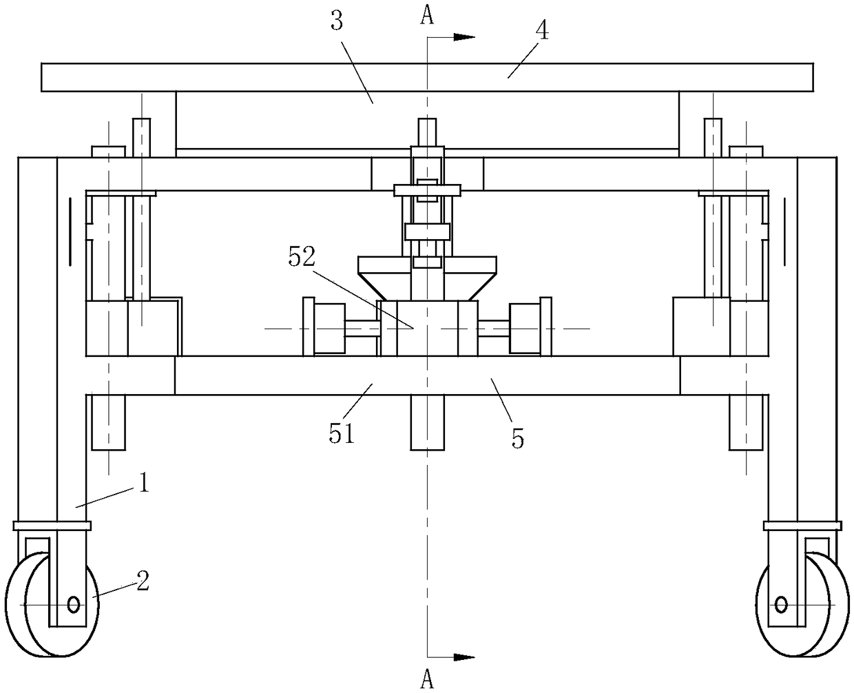
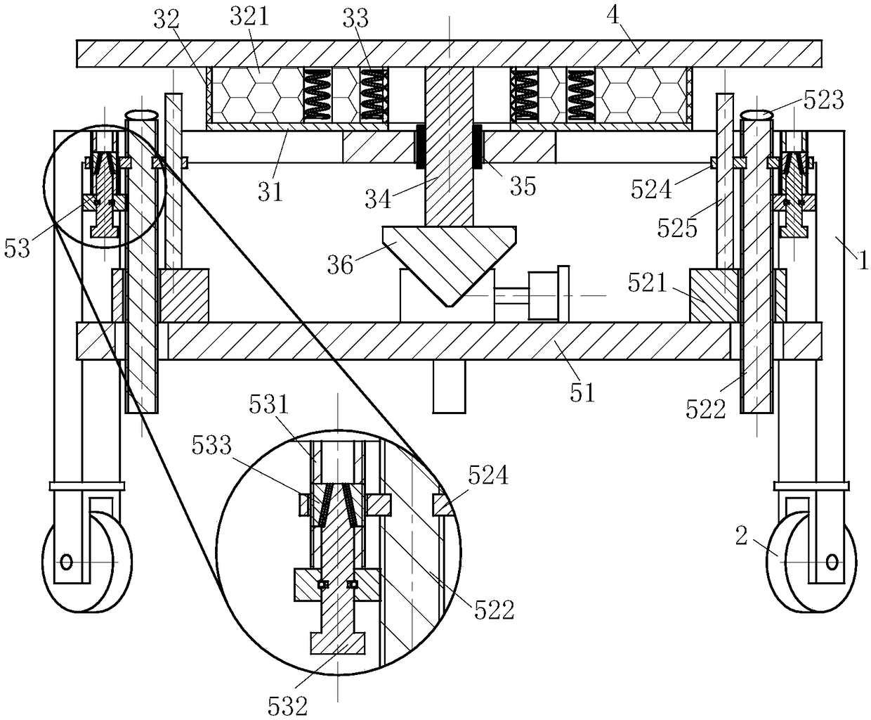
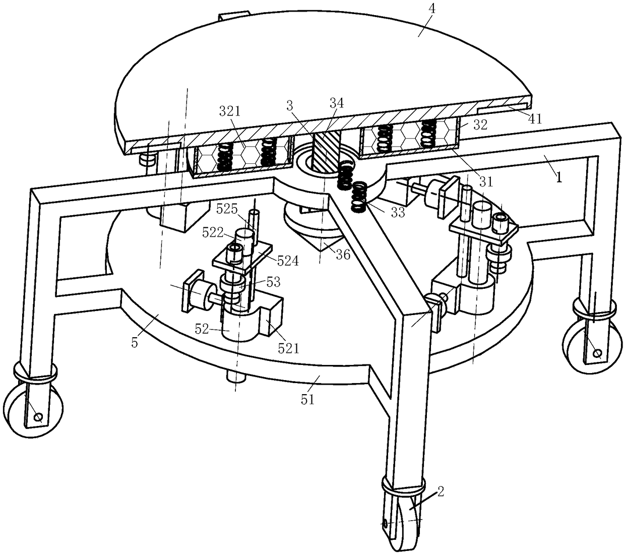
Tightness detection platform for machine parts

A technology for detecting platforms and mechanical parts, applied in the field of measuring tools, can solve problems such as movement, detection platform collision, bolt or screw loosening, etc., to prevent equipment damage, reduce thread clearance, and improve accuracy

Inactive Publication Date: 2018-07-27
张帝
View PDF6 Cites 4 Cited by
  • Summary
  • Abstract
  • Description
  • Claims
  • Application Information

AI Technical Summary

Problems solved by technology

However, no matter what kind of frame is used for the detection platform, the horizontal calibration of the reference platen is realized through repeated fine-tuning of the frame by workers and repeated level measurement of the reference platen. This leveling operation is difficult, Defects such as low efficiency affect the production efficiency of enterprises
[0003]Aiming at the difficulty of level calibration of the testing platform, the protection of the calibrated testing platform becomes particularly important. , it is often easy to cause collision or movement of the detection platform; the shaking of the detection platform will cause the loosening of bolts or screw rods, which will affect the levelness of the reference platen; there are also some mechanical processing plants that need to vibrate and divide materials. In a place with a vibration source, it is costly and inefficient to build a separate inspection room; the inspection platform is placed in the working environment, and it is difficult to avoid the impact of vibration on the inspection platform; therefore, a fastness inspection platform for mechanical parts is invented. , becomes more important

Method used


Image

  • Tightness detection platform for machine parts
  • Tightness detection platform for machine parts
  • Tightness detection platform for machine parts

Examples


Embodiment approach

[0035] As an embodiment of the present invention, the inside of the elastic airbag 32 is provided with a set of supporting airbags 321, and the supporting airbags 321 form a mesh inside the elastic airbag 32. During the automatic balancing process of the measuring table 4, the supporting airbags 321 will measure The steering force of the platform 4 is evenly distributed; and the movement of the measuring platform 4 is slowed down so that the measuring platform 4 can be adjusted smoothly to prevent damage to the equipment caused by violent turbulence.

[0036] As an embodiment of the present invention, the lower surface of the measuring table 4 is provided with an annular weight-reducing groove 41, and the weight-reducing groove 41 is evenly arranged around the center of the circle of the measuring table 4, so that the center of gravity of the measuring table 4 is closer to the center of the circle. Position, improve the accuracy of automatic balance.

[0037] As an embodiment ...


PUM


Abstract

The invention belongs to the technical field of measuring tools, and particularly discloses a tightness detection platform for machine parts. The tightness detection platform for the machine parts comprises a support, walking wheels, a levelling module, a measuring platform and a fixed module; and the support is provided with at least three supporting legs, and the lower end of each of the supporting legs is provided with one walking wheel. The levelling module is connected to the upper portion of the support in a fit mode, and the levelling module comprises a supporting plate, an elastic airbag, a spring, a connecting rod, a cardan joint and a heavy punch. The measuring platform is fixedly connected to the upper end of the levelling module, and the levelling module makes use of gravity to realize the automatic level of the measuring platform. The fixed module is fixedly connected to the middle portion of the support, a wedge-shaped bolt arranged on the fixed module is screwed to realize a clamping block to open to the periphery, a thread gap between a fastening bolt and a fixed plate is reduced, the resistance is improved, and the fastening bolt is prevented from loosing. The tightness detection platform for the machine parts can effectively prevent the detection platform form loosing through fastening of the fixed module.

Description

technical field [0001] The invention belongs to the technical field of measuring tools, in particular to a fastness testing platform for mechanical parts. Background technique [0002] At present, the detection platform commonly used in machining is mainly composed of a reference platen and a frame that supports the reference platen horizontally. There are mainly two types of the frame body. (usually the four corners of the reference platen), and the other is a plurality of screw pairs supported on different support points of the reference platen (usually the four corners of the reference platen). However, no matter what kind of frame is used for the detection platform, the horizontal calibration of the reference platen is realized through repeated fine-tuning of the frame by workers and repeated level measurement of the reference platen. This leveling operation is difficult, Defects such as low efficiency have affected the production efficiency of enterprises. [0003] In...

Claims


Application Information

Patent Timeline
Patent Type & Authority Applications(China)
IPC IPC(8): B25H1/02B25H1/14G01L17/00
CPCB25H1/02B25H1/14G01L17/00
Inventor 张帝何东旭田良奇
Owner 张帝
Learn More