A Distributed Computer Network Clock Synchronization Delay Compensation Method

A computer network and clock synchronization technology, applied in time-division multiplexing systems, electrical components, multiplexing communications, etc., can solve the problems affecting the synchronization accuracy of the system clock, the transmission delay cannot be determined, and improve the system time synchronization. The effect of precision, precise delay, and reduced clock synchronization requirements

Active Publication Date: 2019-07-23
BEIJING MXTRONICS CORP +1
View PDF6 Cites 1 Cited by
  • Summary
  • Abstract
  • Description
  • Claims
  • Application Information

AI Technical Summary

Problems solved by technology

[0009] The present invention provides a distributed computer network clock synchronization delay compensation method. The current distributed system time synchronization technology is timestamped at the MAC layer to determine the delay time, which solves the problem of the system internal physical transceiver (PHY) to the MAC. The transmission delay between them cannot be determined, which affects the synchronization accuracy of the system clock

Method used


Image

  • A Distributed Computer Network Clock Synchronization Delay Compensation Method
  • A Distributed Computer Network Clock Synchronization Delay Compensation Method
  • A Distributed Computer Network Clock Synchronization Delay Compensation Method

Examples


Embodiment Construction

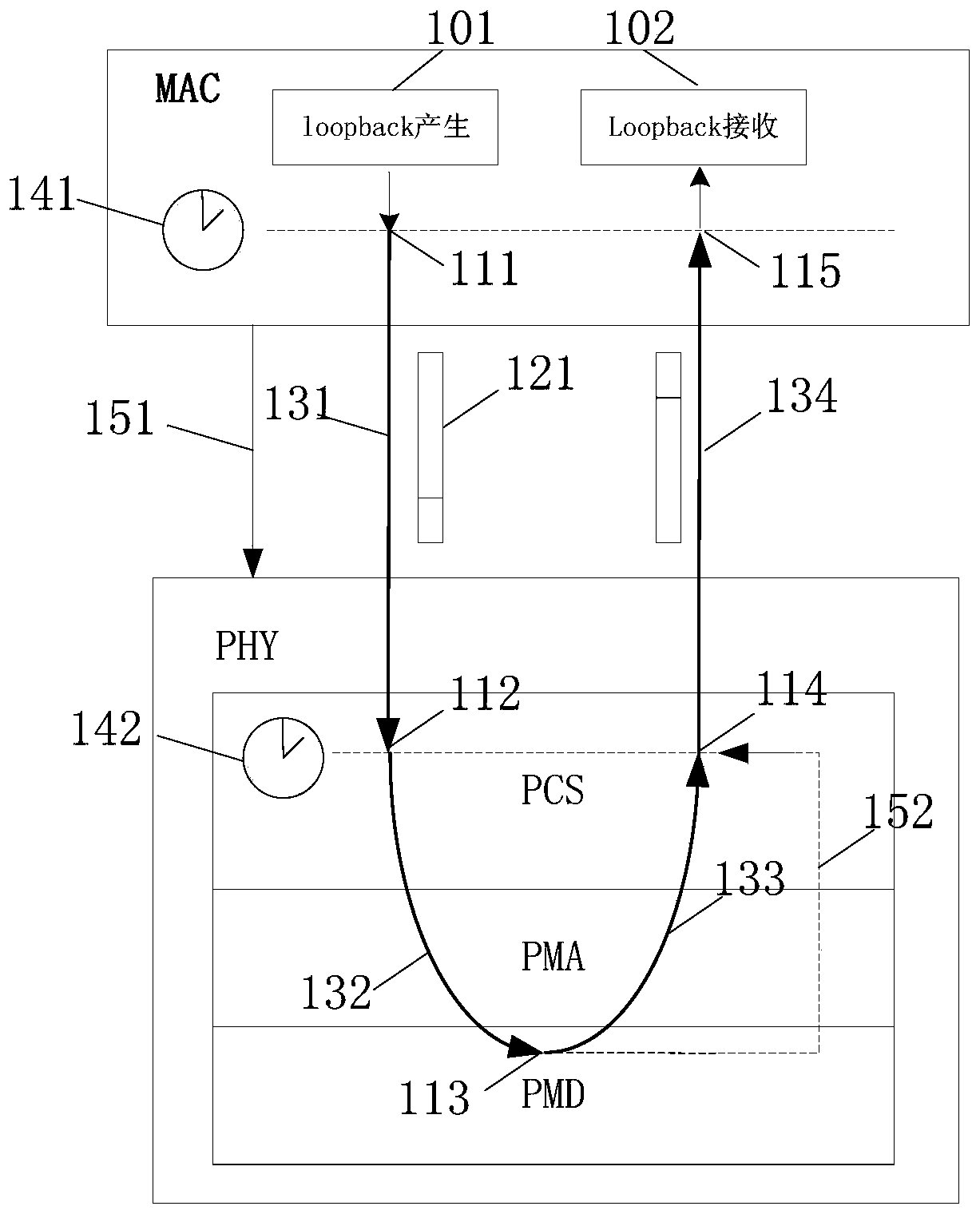
[0056] The present invention assumes that the link between the MAC and the PHY is symmetrical, and the path of receiving and sending inside the PHY chip is asymmetrical. In the loopback mode of the PHY, it is realized by sending a loopback frame through the MAC layer, and the calculation is performed after power-on and reset, and the chain There is no need to repeat the calculation when the circuit works normally, and only some adaptive modifications need to be made to the MAC layer and the PHY chip. Specifically include:

[0057] The mode setting (151), provided by the MAC layer, needs to combine the PHY state configuration of the application layer with the PHY state configuration generated by the delay calculation module to generate a new PHY state configuration signal.

[0058] The PHY works in loopback mode, the receiver between the PHY and the network cable will be turned off, and the PHY will not receive data from the network cable. This mode is used for the normal test ...


PUM


Abstract

The invention discloses a distributed computer network clock synchronization delay compensation method, which is used for calculating delay of an asymmetric path between an MAC layer and a PHY layer and compensating the value into the synchronous delay of a distributed clock so as to improve the clock synchronization precision. While calculating, the MAC layer constructs a special loopback frame and issues the special loopback frame to the PHY, the frame is forwarded to a receiving channel after passing through the PCS, the frame is uploaded to the MAC through the PMD, the PMA and the PCS, andtime stamps are printed on the passing key points; finally, accurate calculation of receiving and sending path delay between the MAC and the PHY is completed through the time stamps recorded in the loopback frame load, namely a delay compensation value of the distributed computer network synchronization technology. According to the method, the time delay between the asymmetric paths in the systemdevice can be accurately calculated, the blank of the distributed clock synchronization technology in the segment of delay is made up, and synchronization precision of the distributed clock synchronization technology can be further improved after delay compensation is carried out.

Description

technical field [0001] The invention relates to a distributed computer network clock synchronization delay compensation method, which is suitable for clock synchronization in a distributed computer network system and belongs to the technical field of delay compensation. Background technique [0002] With the transformation of the communication mode of the integrated electronic system from the bus to the network and the development of the system architecture from the joint type to the IMA and DIMA architecture, more and more attention is paid to the time-triggered network system. The operation of the time-triggered system depends on the global time base The effectiveness of any time base will cause the system to fail. In safety-critical applications, fault tolerance based on a time base of known accuracy is very important. Ethernet time synchronization technology is the key to time-triggered systems. Time synchronization technology is currently widely used in aerospace, aviat...

Claims


Application Information

Patent Timeline
Patent Type & Authority Patents(China)
IPC IPC(8): H04J3/06
CPCH04J3/0667
Inventor 闫攀赵沛张奇荣陶舒婷牛建泽毛雅欣
Owner BEIJING MXTRONICS CORP
Why Eureka
Try Eureka