A low-power two-way real-time wireless sensing method

A technology of wireless sensing and low power consumption, applied in the field of wireless sensing, can solve the problems of poor real-time performance, high power consumption, no receiving unit, etc., and achieve the effect of real-time performance improvement, low power consumption, and low power consumption performance

Active Publication Date: 2017-12-19
NANJING NARI GROUP CORP +1
View PDF3 Cites 0 Cited by
  • Summary
  • Abstract
  • Description
  • Claims
  • Application Information

AI Technical Summary

Problems solved by technology

However, this kind of WDAU product cannot receive the commands sent by CMD in real time for measurement, and even some WDAU products only have a sending unit and no receiving unit.
[0006] In order to further reduce the power consumption of the entire system, some products (product 2) use the clock synchronization between CMD and WDAU to avoid the CMD being in the waiting state, thereby reducing the power consumption of CMD, but this product has extremely high requirements for clock synchronization , once the clock is out of sync, it will often cause the system to fail to work properly
[0007] The above two products can only provide one-way data communication, and cannot realize the control of CMD to WDAU. For this reason, some products (product 3) have made improvements on this basis, using CMD to temporarily store the commands that need to be issued. On the one hand, CMD After receiving the data sent by WDAU, immediately send the temporarily stored command to WDAU; on the other hand, after sending out the measured data, WDAU does not immediately shut down the wireless transceiver system, but waits for a certain length of time to judge whether there is a CMD sent The control command of this product can realize the function of setting or modifying parameters remotely, but the real-time performance of modifying parameters of this product depends entirely on the measurement interval of WDAU. The longer the measurement interval, the worse the real-time performance
[0008] According to the above product technical implementation methods, it can be seen that because the CMD of product 1 is usually in the state of wireless waiting for reception, the power consumption is relatively large, and the low power consumption characteristics of the system are only reflected in the sensor nodes, and low power consumption at the system level is not realized; Moreover, since the wireless sensor sub-node is usually in a dormant state with extremely low power consumption, remote control or parameter configuration and other operations cannot be realized. The wireless sensor sub-node generally adopts the working method of timing collection and active reporting, and can only realize the communication from WDAU to CMD. For one-way wireless communication, in order to achieve low power consumption, the interval between regular collection and active reporting should not be too small, generally not less than 5 minutes, so in some fast-changing parameter monitoring applications, the real-time performance of data cannot be guaranteed
[0009] Product 2 reduces the power consumption of CMD through clock synchronization. This product, like product 1, can only realize one-way wireless communication from WDAU to CMD
In addition, this product has too high requirements for clock synchronization, and clock out of sync will have a catastrophic impact on the normal operation of the system.
[0010] Product 3 realizes the two-way wireless communication function, so that it can realize the function of setting or modifying WDAU parameters through CMD, but the real-time performance of modifying parameters depends entirely on the measurement interval of WDAU. The longer the measurement interval, the worse the real-time performance

Method used


Image

  • A low-power two-way real-time wireless sensing method
  • A low-power two-way real-time wireless sensing method
  • A low-power two-way real-time wireless sensing method

Examples


Embodiment Construction

[0028] The present invention will be further described in detail below in conjunction with the drawings.

[0029] In order to help clearly explain the technical solution of the present invention, the technical terms involved are first explained as follows:

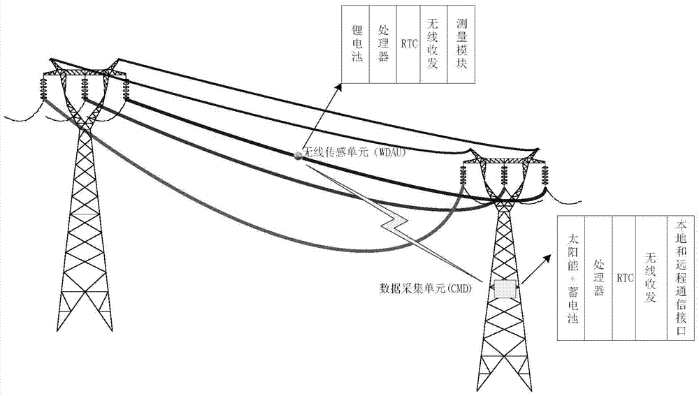
[0030] RTC (Real-Time Clock): Real-time clock. The main function is to provide a stable clock signal for subsequent circuits. The main functions are: clock & calendar, alarm clock, periodic interrupt output, 32KHz clock output.

[0031] Power Line Supervisory: Power Line Supervisory is a general term that uses advanced technology to automatically monitor and scientifically manage transmission lines, and is also one of the important foundations for the realization of smart grids. On-line monitoring of transmission lines is a complex system project. It takes the on-line monitoring system of transmission lines as the core, and involves the supporting requirements for the primary grid and equipment of the transmission grid, the comp...


PUM


Abstract

The invention discloses a low-power consumption bidirectional real-time wireless sensing method. The low-power consumption bidirectional real-time wireless sensing method includes a plurality of sampling periods, and the sampling period includes that a CMD starts a wireless receiving module at the time T1 according to a set sampling time parameter; after passing the time delay of which the length is TD, a WDAU is started to enter a measuring state; after the WDAU finishes measuring, the WDAU enters a wireless receiving/transmitting state at the time T2+TSM; the WDAU immediately turns off the wireless module to enter a low-power consumption dormant state after finishing communicating with the CMD; the CMD turns off the wireless module to enter the low-power consumption dormant state after finishing communicating with the WDAU and passing the time delay of which the length is TD. The low-power consumption bidirectional real-time wireless sensing method realizes the synchronous work of the WDAU and CMD, and accordingly both the WDAU and CMD can locate at the low-power consumption dormant state at ordinary times; the low-power consumption bidirectional real-time wireless sensing method increases a plurality of timed receiving time slots for the WDAU in the measuring gap, and the bidirectional wireless communication is realized based on guaranteeing the low power consumption of the WDAU.

Description

Technical field [0001] The invention relates to a wireless sensing method, in particular to a low-power two-way real-time wireless sensing method. Background technique [0002] In the online monitoring system of power transmission lines, the wireless data acquisition unit (WDAU) installed on the overhead power transmission line generally communicates with the condition monitoring device (CMD) installed on the tower in a wireless manner. WDAU is generally composed of lithium battery, processor, real-time clock (RTC), wireless transceiver, measurement and other modules; CMD is generally composed of solar + battery power supply, processor, RTC, wireless transceiver, local and remote communication interface and other modules. Both WDAU and CMD constitute an online monitoring device for transmission lines. The typical schematic diagram of on-site installation is as follows figure 1 Shown. [0003] At present, this type of wireless data acquisition unit adopts two power supply modes: on...

Claims


Application Information

Patent Timeline
Patent Type & Authority Patents(China)
IPC IPC(8): H04W52/02G08C17/02
CPCG08C17/02H04W52/0209Y02D30/70
Inventor 曹翊军曹年红蓝彦王亦宁周海松郭宝龙李秋水马贵林魏敏祥钱昊
Owner NANJING NARI GROUP CORP
Why Eureka
Try Eureka