Clock and data recovery circuit without reference clock input

A reference clock and recovery circuit technology, applied in the direction of electrical components, automatic power control, etc., can solve the problems of frequency tracking loop and phase tracking loop mutual interference, FD630 can not be adjusted normally, high production cost requirements, etc., to achieve Widen the operating frequency range, avoid lock-out phenomenon, and save chip area

Inactive Publication Date: 2018-07-24
BEIJING MXTRONICS CORP +1
View PDF4 Cites 9 Cited by
  • Summary
  • Abstract
  • Description
  • Claims
  • Application Information

AI Technical Summary

Problems solved by technology

[0004] use Figure 5a There are two problems in the design scheme. One is that the frequency tracking loop and the phase tracking loop may interfere with each other and affect the circuit locking; the other is that when the input data is continuous with the same pattern, inter-symbol interference may cause the FD630 to fail to adjust normally.
In order to overcome the above problems, it is necessary to ensure that the bandwidth of the frequency-locked loop is much smaller than the bandwidth of the phase-locked loop during design, resulting in a longer locking time of the circuit
[0005] To optimize the system lock time, you can use Figure 5b The design scheme, frequency-locked loop bandwidth and phase-locked loop bandwidth can be adjusted independently, but two sets of independent charge pump CP650, filter LF660, will increase a lot of chip area, and require high production cost

Method used


Image

  • Clock and data recovery circuit without reference clock input
  • Clock and data recovery circuit without reference clock input
  • Clock and data recovery circuit without reference clock input

Examples


Embodiment Construction

[0047] The specific embodiments of the present invention will be described in detail below in conjunction with the accompanying drawings.

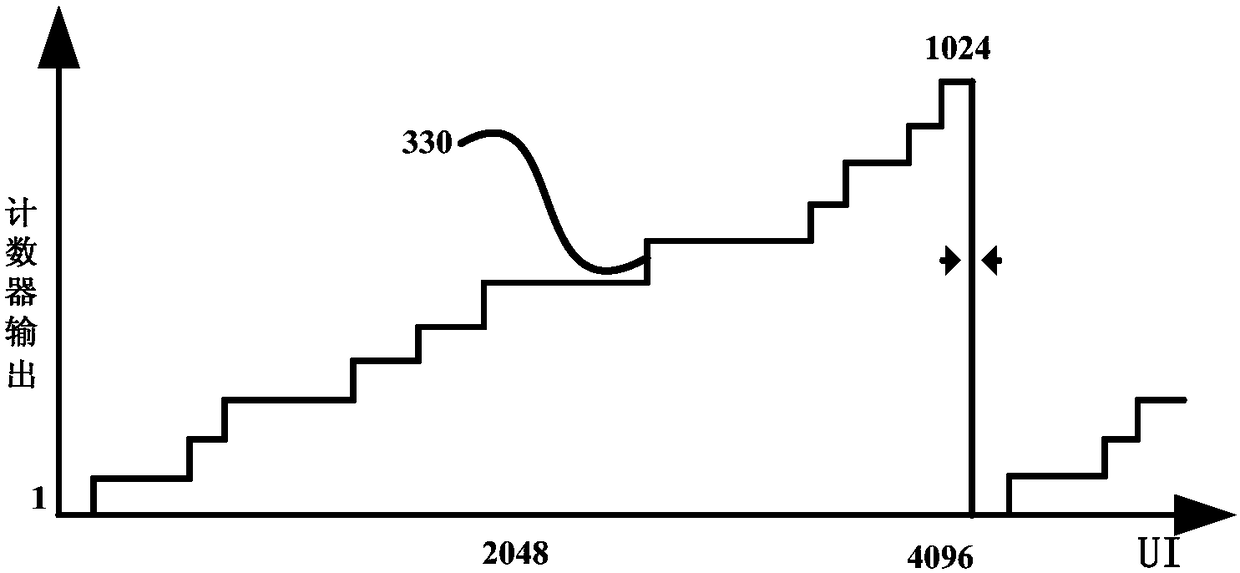
[0048] The invention provides a clock and data recovery circuit applied to high-speed interface circuits without reference clock input, combined with figure 1 The circuit includes high speed sampler 150, high speed sampler 210, buffer 110, binary phase detector 220, counter 120, count 160, comparator 130, digital filter 230, current steering DAC 190, voltage manager 180, low phase noise wide frequency VCO 170 and pseudo binary search algorithm module 140 .

[0049]The high-speed samplers 150 and 210 have the same structure, including two parts of a sense amplifier and an RS latch. The sampling rate is greater than 10Gbps. The Clk terminal is connected to the output of the VCO. When the Clk is low, the sampling unit is in the reset state, and the RS latch is in the Hold the state, the output remains unchanged from the previous state; when...


PUM


Abstract

The invention relates to a clock and data recovery circuit without reference clock input. The circuit comprises a high-speed sampler, a binary phase discriminator, a counter, a comparator, a pseudo-binary searching algorithm, a digital filter, a voltage regulator, a current steering DAC and a low-phase noise width frequency VCO; the clock and data recovery circuit adopts dual-ring architecture, the quick locking of the frequency is performed by coarsely regulating a frequency-locking loop to guarantee that the sampling clock frequency is approximately equal to the rate of inputting data; afterthe frequency-locking loop regulation is finished, the circuit can realize the phase locking by finely regulating a phase-locking loop to guarantee that the sampling clock is located at the middle location of the data, thereby accurately recovering the clock and data information. Through the control way disclosed by the invention, the wide rate range work can be realized without requiring an external reference clock, and the circuit has strong jittering tolerance capacity and quick locking capacity.

Description

technical field [0001] The invention relates to a clock data recovery circuit without a reference clock input, in particular to a clock data recovery circuit controlled by a pseudo-binary search algorithm and a digital filter, and belongs to the field of high-speed interface circuit design. Background technique [0002] The clock data recovery circuit is a key module to realize high-speed serial communication. It recovers the clock signal from the serial data, finds the best sampling point of the data through the adjustment of the circuit, recovers the data through the retiming of the data, eliminates the jitter introduced in the data transmission process, and its performance has a great impact on the entire high-speed serial The line transmission system has a crucial influence. The existing clock input CDR structure needs to pre-configure the data transmission rate, which limits the flexibility of product application. [0003] No reference clock input CDR structure of the...

Claims


Application Information

Patent Timeline
IPC IPC(8): H03L7/08H03L7/099
CPCH03L7/0807H03L7/099
Inventor 李全利时飞边强李建成
Owner BEIJING MXTRONICS CORP
Why Eureka
Try Eureka