
A five-axis compound machining center with horizontal cradle structure

A composite machining center, cradle technology, applied in metal processing equipment, metal processing mechanical parts, manufacturing tools, etc., can solve the problems of slow start, machine vibration, large machine tool bending, etc., to improve processing efficiency, stable and reliable operation, High dynamic response effect

Active Publication Date: 2020-06-26
KEDE NUMERICAL CONTROL CO LTD
View PDF8 Cites 0 Cited by
  • Summary
  • Abstract
  • Description
  • Claims
  • Application Information

AI Technical Summary

Problems solved by technology

[0004] At present, the horizontal machining center adopts a single ball screw drive on the turntable drive, so that the driving force cannot accurately act on the center of gravity of the moving parts, so it is easy to produce a torsional tendency during high-speed chip cutting, causing vibration of the machine tool and making the machine tool larger bending and deformation of the parts, and at the same time have a certain impact on the accuracy and life of the turntable
Moreover, the cradle workbench is mostly mechanically driven, slow to start, and there is a backlash when changing direction, the positioning accuracy and repeat positioning accuracy are low, and the workpiece is prone to joint marks

Method used


Image

  • A five-axis compound machining center with horizontal cradle structure
  • A five-axis compound machining center with horizontal cradle structure
  • A five-axis compound machining center with horizontal cradle structure

Examples


Embodiment Construction

[0020] In order to make the purpose, technical solutions and advantages of the embodiments of the present invention clearer, the technical solutions in the embodiments of the present invention will be clearly and completely described below in conjunction with the drawings in the embodiments of the present invention. Obviously, the described embodiments It is a part of embodiments of the present invention, but not all embodiments. Based on the embodiments of the present invention, all other embodiments obtained by persons of ordinary skill in the art without making creative efforts belong to the protection scope of the present invention.

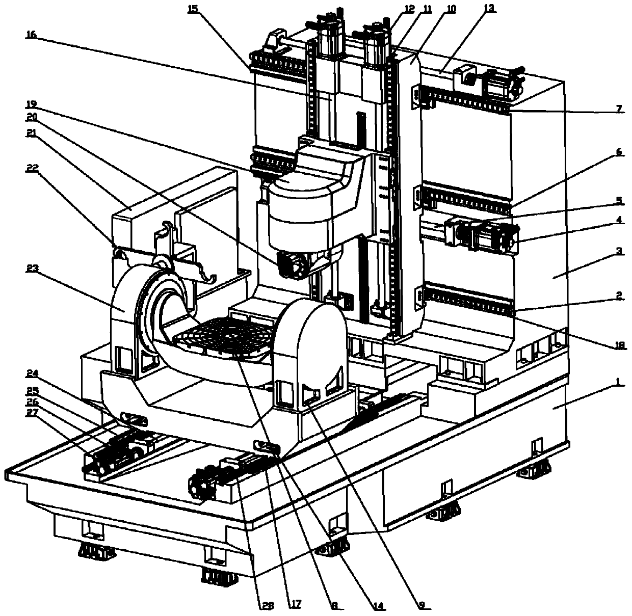
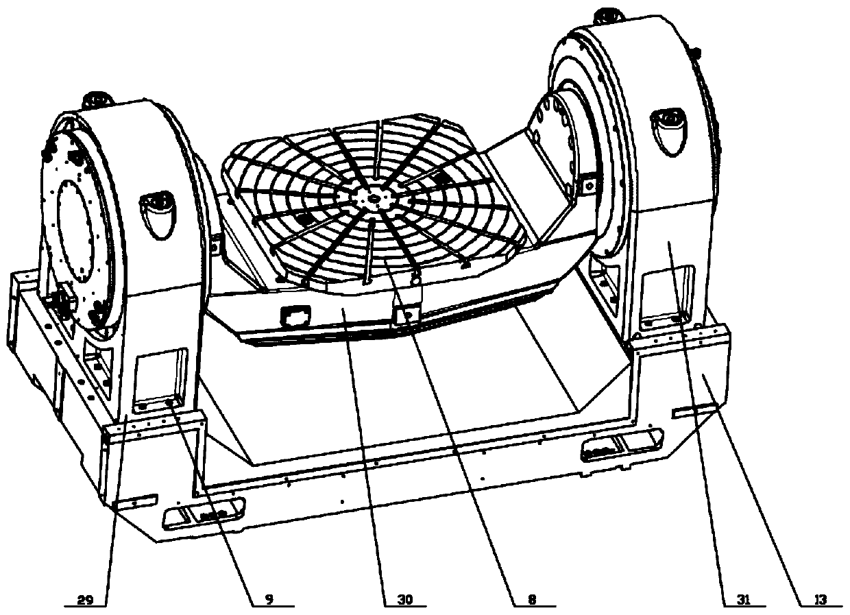
[0021] Such as figure 1 and figure 2 As shown, the horizontal cradle structure five-axis compound machining center of this embodiment includes:

[0022] Bed 1, column 3, Z-axis guide rail 26, cradle support seat 23, Z-axis slider 17, X-axis guide rail, X-axis screw, X-axis slider 18, sliding saddle 10, Y-axis guide rail 11, headstock 19 ,...


PUM


Abstract

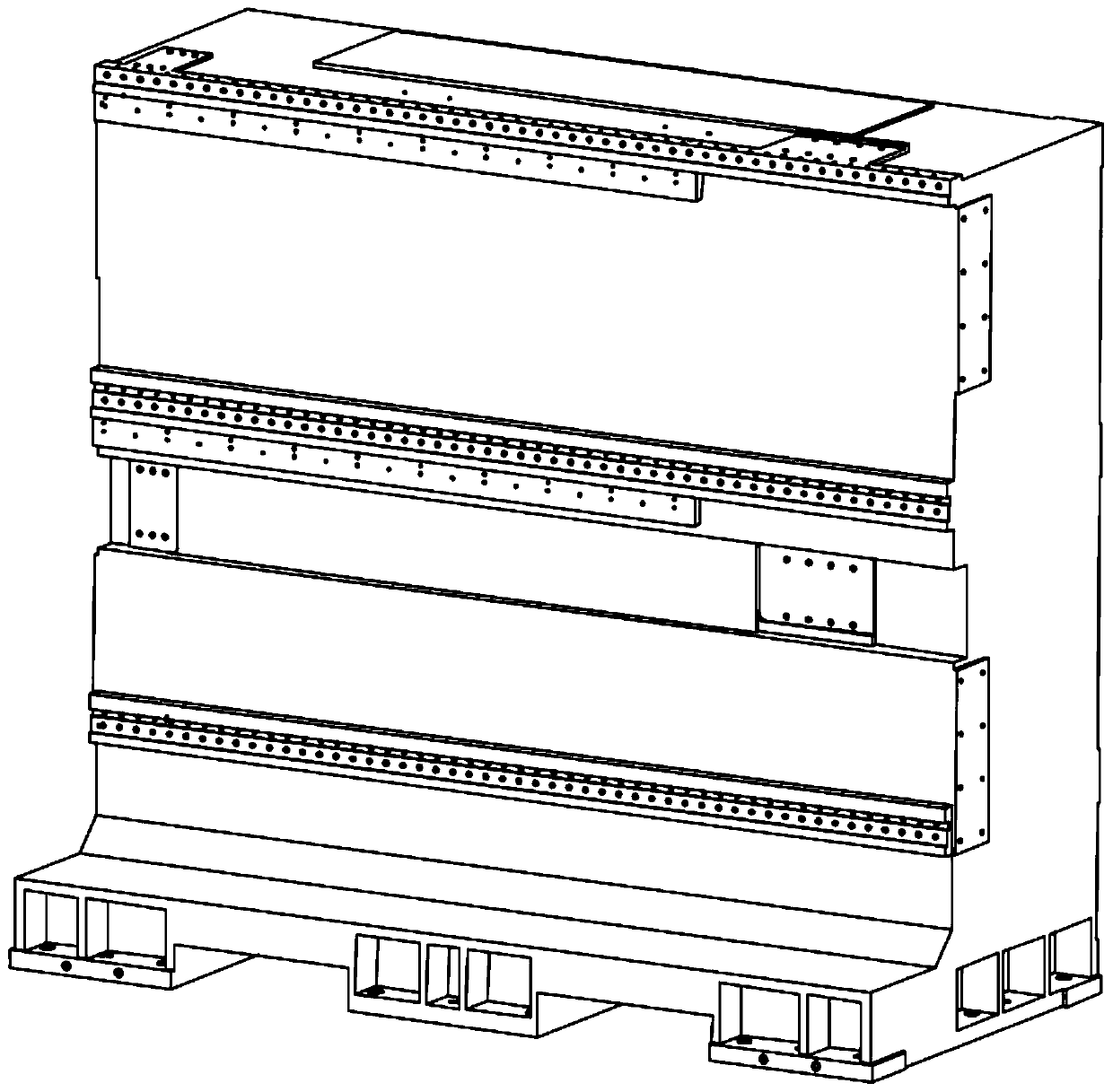
The invention discloses a five-axis compound machining center of a horizontal cradle structure. The five-axis compound machining center comprises a machine body arranged horizontally, and the fore-and-aft movement of a cradle workbench on the machine body is the Z-axis movement. A column is installed at the tail of the machine body, and the left-and-right movement of a sliding saddle on the columnis the X-axis movement. The up-and-down movement of a spindle driven by a spindle box on the sliding saddle is the Y-axis movement. The movement of a cradle around the X axis is the A-axis movement.The movement of the workbench around the Y axis is the B-axis movement. The X axis, the Y axis, the Z axis, the A axis and the B axis are linked so that the cutting and machining of complex curved surfaces can be achieved. The left side of the machine body is provided with a tool magazine and a tool changing manipulator, and the automatic tool change of the machining center is achieved; the production efficiency is improved. The middle part of the machine body is used for chip removal, and the column is of an L-shaped structure; the center of gravity of moving components of the sliding saddleand the spindle is ensured within the column all the time; and the integral rigidity is improved. The structure is applicable for high-efficiency and high-precision machining of aluminum alloy aviation structural parts and cylinder parts. The requirements of the domestic aerospace industry for high-efficiency and high-precision machining equipment for the aluminum alloy aviation structural parts are met.

Description

technical field [0001] The invention relates to the field of metal processing, in particular to a five-axis compound machining center with a horizontal cradle structure. Background technique [0002] The horizontal five-axis machining center is a double-oscillating head horizontal five-axis machining center with two rotating axes at the spindle end, and a horizontal five-axis machining center with a single-oscillating head and a rotary table structure with one rotating axis arranged at the spindle end and the table end. In the center, in order to meet the needs of large cutting force and high torque for cutting workpieces, the structural size of the swing head is generally designed to be relatively large, and the structure is also relatively complicated, resulting in long overhangs and poor rigidity of the swing head and spindle. [0003] Horizontal cradle structure five-axis compound machining center, the advantage of this structure is that the spindle structure is relative...

Claims


Application Information

Patent Timeline
Patent Type & Authority Patents(China)
IPC IPC(8): B23Q1/62B23Q1/01B23Q11/00
CPCB23Q1/015B23Q1/626B23Q11/0042
Inventor 陈虎侯延星张传思范春宏时冬梅赵立新张忠涛孙永杰汤洪涛
Owner KEDE NUMERICAL CONTROL CO LTD
Learn More