Rocket engine tail jet flow simulation method and system

A rocket engine and simulation method technology, applied in the field of simulation model establishment, to achieve the effect of improving accuracy and reducing errors

Active Publication Date: 2018-07-20
BEIJING AEROSPACE PROPULSION INST
View PDF4 Cites 15 Cited by
  • Summary
  • Abstract
  • Description
  • Claims
  • Application Information

AI Technical Summary

Problems solved by technology

[0004] The technical problem solved by the present invention is: to overcome the deficiencies of the prior art, to provide a rocket engine tail jet flow simulation method and system, and to solve the problem that the existing turbulent flow models cannot accurately simulate the shear mixing of supersonic compressible jets

Method used


Image

  • Rocket engine tail jet flow simulation method and system
  • Rocket engine tail jet flow simulation method and system
  • Rocket engine tail jet flow simulation method and system

Examples


specific Embodiment approach

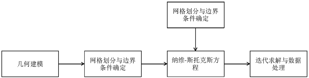
[0041] The overall flow field of rocket engine tail jet simulation is as follows: figure 1 As shown, the main steps are:

[0042] 1. Establish geometric modeling and meshing

[0043] According to the geometric parameters of the nozzle, the 3D modeling of the contraction and expansion section of the engine nozzle and the external jet area is carried out by using the Solidwork software.

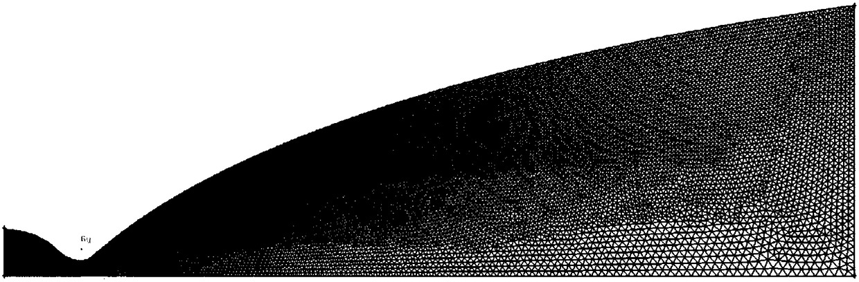
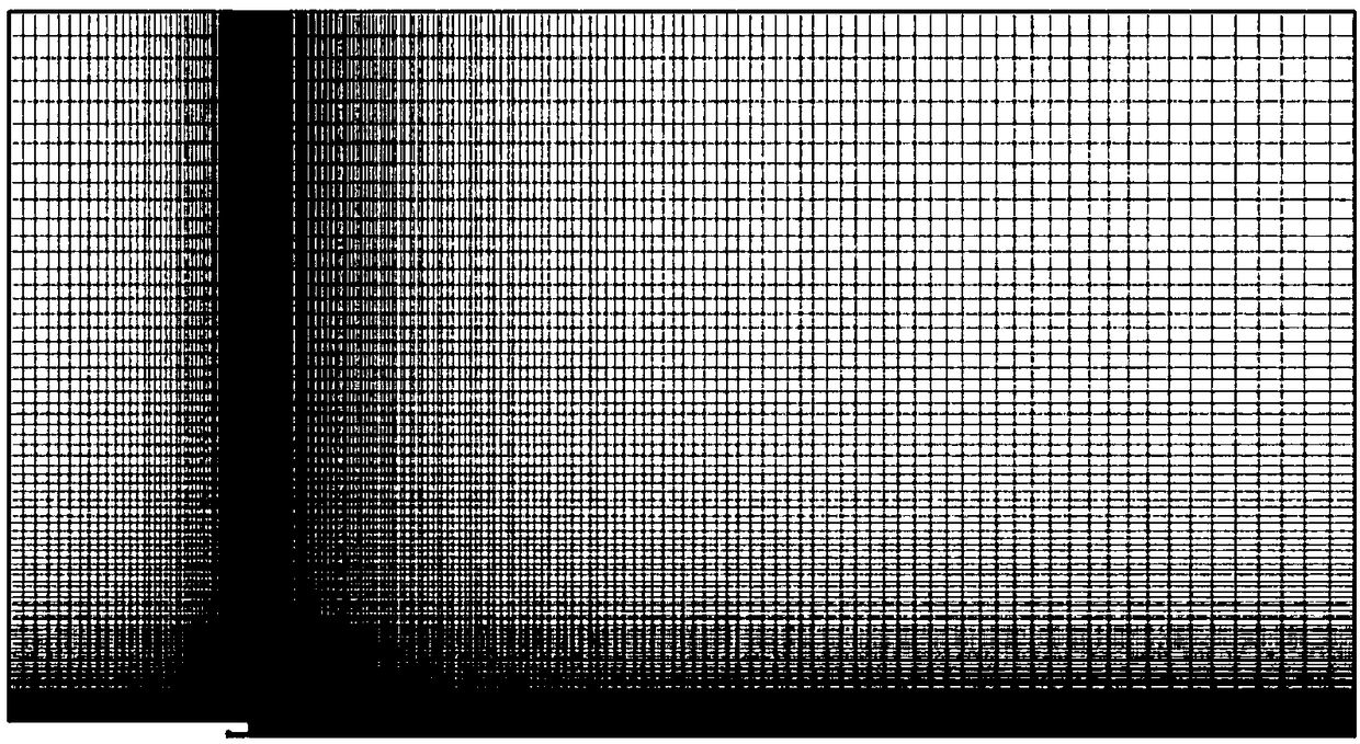
[0044] 2. Divide computational grid and determine boundary conditions

[0045] Using Ansys ICEM software to mesh the established geometric model, the generated mesh is as follows: figure 2 shown. The pressure, temperature, composition and other parameters in the combustion chamber of the engine are the initial boundary conditions of the nozzle pressure inlet, and the ambient pressure and ambient temperature are the initial boundary conditions of the nozzle outlet. The wall of the nozzle is smooth and insulated without slip. The gas in the nozzle is compressible, which satisfies the ideal g...


PUM


Abstract

The invention relates to a rocket engine tail jet flow simulation method and system. The method includes the steps of (1), establishing a three-dimensional geometric model with the size same as a rocket engine jet pipe; (2), conducting grid partition and encryption on the three-dimensional geometric model to determine boundary conditions; (3), establishing a calculation model to ensure that a tailjet flow process satisfies a viscosity Navier-Stokes equation; (4), conducting iterative solution on a rocket engine tail jet flow model by using a computational model, and completing the simulationprocess of rocket engine tail jet flow. A temperature-corrected SST k-omega turbulence model is adopted for calculating the rocket engine tail jet flow, the defect that existing turbulence models cannot accurately predict supersonic compressible jet flow under a large temperature gradient is remedied, the accuracy of a simulation result is significantly improved, and an error between the simulation result and an experimental result is reduced to 1%.

Description

technical field [0001] The invention belongs to the field of rocket engine tail jet flow simulation and relates to the establishment of a tail jet flow simulation model. Background technique [0002] The rocket engine converts the chemical energy of the medium into internal energy through the combustion reaction, and the high-temperature and high-pressure gas produced generates thrust through the expansion of the nozzle. Therefore, the characteristics of the tail jet flow can directly affect the main technical indicators such as the thrust and specific impulse of the engine. At present, the research methods of rocket engine tail jet flow mainly include: experimental test method and simulation analysis method; among them, due to the limitation of test conditions and the immaturity of measurement technology, it is difficult to fully and intuitively understand the jet flow characteristics of rocket engine tail nozzle only through experimental testing . In recent years, with th...

Claims


Application Information

Patent Timeline
Patent Type & Authority Applications(China)
IPC IPC(8): G06F17/50
CPCG06F30/15G06F30/17G06F30/20Y02T90/00
Inventor 李子亮薛薇吴瑾清胡慧武小平刘业奎
Owner BEIJING AEROSPACE PROPULSION INST
Why Eureka
Try Eureka