
Loading manipulator of PMC threading machine

A technology of thread turning machine and manipulator, which is applied in metal processing equipment, tangential feeding devices, manufacturing tools, etc., can solve the problems of complex structure, complicated maintenance and repair, and it is difficult to ensure the clamping force.

Active Publication Date: 2018-07-20
SHANGHAI BAOSTEEL IND TECHNOLOGICAL SERVICE
View PDF5 Cites 7 Cited by
  • Summary
  • Abstract
  • Description
  • Claims
  • Application Information

AI Technical Summary

Problems solved by technology

[0003]Although the existing PMC threading machine has high efficiency and stable quality in the turning process, the existing PMC threading machine needs manual loading and unloading of workpieces. The work of clamping and disassembly has the following disadvantages: 1) It is difficult to ensure the clamping force when clamping workpieces such as pipe sleeves, and it is easy to cause the workpiece to be clamped and deformed; 2) The iron filings turned by the wire turning machine are sharp and hard , it is easy to scratch the operator; 3) The existing loading, unloading and clamping devices are usually driven by hydraulic pressure, so there are disadvantages such as complicated maintenance and repair, poor response sensitivity, and complicated structure.

Method used


Image

  • Loading manipulator of PMC threading machine
  • Loading manipulator of PMC threading machine
  • Loading manipulator of PMC threading machine

Examples


Embodiment Construction

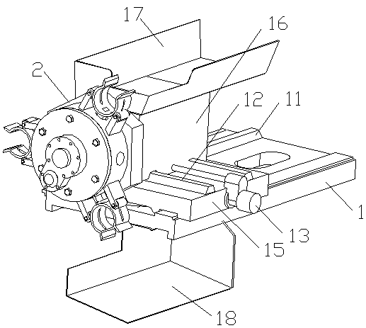
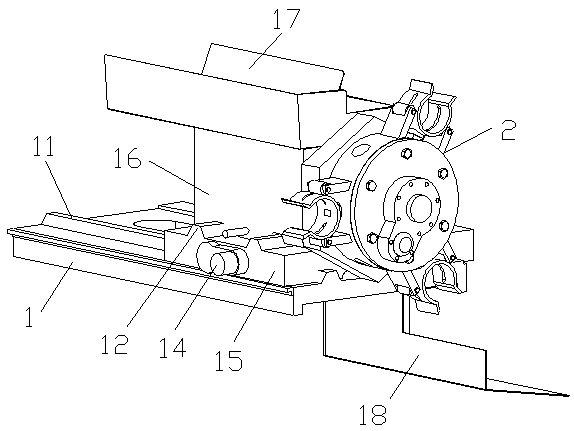
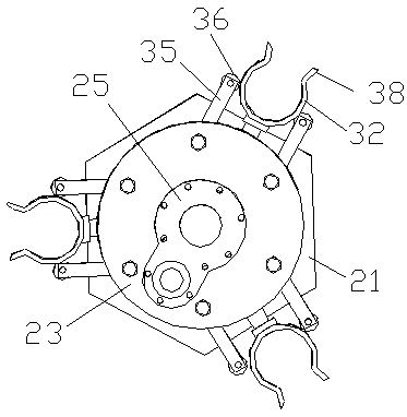
[0024] Example Figure 1 to Figure 7 As shown, the PMC threading machine feeding manipulator of the present invention comprises frame 1, transverse guide rail 11, longitudinal guide rail 12, transverse drive motor 13, longitudinal drive motor 14, middle pallet 15, corner motor 16, feeding tray 17, blanking Disk 18 and clamping mechanism 2, described transverse guide rail 11 is arranged on the top surface of described frame 1, and described transverse drive motor 13 and longitudinal drive motor 14 are respectively arranged on the both sides of described middle support plate 15, and described middle support Plate 15 is arranged on described transverse guide rail 11 and moves back and forth along described transverse guide rail 11 under the drive of transverse driving motor 13, and described longitudinal guide rail 12 is arranged on the top surface of described middle support plate 15, and described corner motor 16 is arranged on The longitudinal guide rail 12 also moves back and...


PUM


Abstract

The invention discloses a loading manipulator of a PMC threading machine. According to the manipulator, a middle support plate which is capable of reciprocating transversely is arranged on a rack; a longitudinal driving motor which is capable of reciprocating longitudinally is arranged on the middle support plate; a rotation shaft of the longitudinal driving motor is connected with a clamping mechanism; the clamping mechanism comprises a connection disk, a mounting sleeve, an end disk, a can, a cam driving motor and a plurality of clamping components; the connection disk, the mounting sleeve and the end disk are coaxially connected in sequence; a rotation shaft of an angle motor drives the connection disk; the cam is located at the inner ring of the mounting sleeve; the cam driving motor is arranged on the side surface of the end disk and drives the cam to rotate; the mounting sleeve is equidistantly provided with a plurality of through holes along the radial direction, one side of themounting sleeve is a guiding hole and the opposite side is a process hole; and the clamping component is arranged in the guiding hole and is driven by the cam and is used for clamping a workpiece bya clamping ring. The manipulator is capable of overcoming the workpiece clamping defects of traditional threading machines, effectively improving the workpiece clamping precision and efficiency, and preventing scrap iron from hurting people and scratching the workpiece surfaces, and is convenient to maintain and overhaul so as to improve the operation reliability of the threading machine.

Description

technical field [0001] The invention relates to a feeding manipulator of a PMC threading machine. Background technique [0002] Threading machine is an indispensable mechanical equipment for thread processing of shaft and pipe sleeve workpieces. With the continuous development of mechanical equipment automation, mass production has become the mainstream of modern processing industry. Therefore, automatic threading machine is also constantly Upgrade improvements. [0003] Although the existing PMC threading machine has high efficiency and stable quality in the turning process, the existing PMC threading machine needs manual clamping and disassembly work in terms of flexible loading and unloading of workpieces, which has the following disadvantages: 1) Tube sleeves When the workpiece is clamped, it is difficult to ensure the clamping force, and it is easy to cause the workpiece to be clamped and deformed; 2) Because the iron filings turned by the threading machine are sharp a...

Claims


Application Information

Patent Timeline
Patent Type & Authority Applications(China)
IPC IPC(8): B23G11/00
CPCB23G11/00
Inventor 项允
Owner SHANGHAI BAOSTEEL IND TECHNOLOGICAL SERVICE
Learn More