
Novel wire and application thereof

A wire, a new technology, applied in the new wire and its application field, can solve the problems of limited elongation and deformation of ceramic fibers, reduce tower distance, large thermal sag, etc., achieve the effect of superior weight ratio, reduce wind resistance and ice load

Pending Publication Date: 2018-07-17
深圳市圣龙新材料科技有限公司
View PDF4 Cites 0 Cited by
  • Summary
  • Abstract
  • Description
  • Claims
  • Application Information

AI Technical Summary

Problems solved by technology

Moreover, due to the imbalance of energy distribution and the development of the east and west, it is urgent to solve the bottleneck problem of high-power and long-distance energy transmission.
Although the construction of ultra-high voltage has partially alleviated this contradiction, due to the limitation of the carrying capacity of traditional steel-reinforced aluminum stranded wires, transmission lines have been unable to withstand the rapid expansion of transmission capacity, and power transmission has become a "bottleneck" for the development of the power industry.
[0003] ACSR common aluminum stranded wire has its disadvantages: it cannot operate at high temperature, which limits the capacity of the wire and the current carrying capacity is limited; the steel core is heavy, the coefficient of thermal expansion is large, and the thermal arc sag is large; High tower, high engineering cost
Its defect: the conductor core is made of glass fiber and carbon fiber composite materials, the modulus of the load-bearing core is much smaller than that of the steel core, forming a large ice area sag, large spans and large conductors due to their own weight, or due to ice, wind resistance Such loads form a large sag, which leads to the heightening of the tower or the increase of the tower, the reduction of the distance between the towers, and the increase of the project cost; the bearing core has insufficient pressure resistance, and it is easy to split and damage when the radial pressure is applied, requiring expensive Special fittings; when bending, the load-bearing core, especially the carbon fiber load-bearing core, is easy to break due to the remaining stress; the composite material is exposed to the environment, and the service life is greatly affected by the environment, especially the hydration and oxidation decomposition of the composite material core. severe damage to
Due to the extremely limited elongation and deformation of ceramic fibers, even if the ceramic fiber wires are multi-strand small round wires, similar to carbon fiber wires, they are still easy to damage and break when encountering sharp-angle bending, causing huge safety hazards

Method used


Image

  • Novel wire and application thereof
  • Novel wire and application thereof
  • Novel wire and application thereof

Examples


Embodiment 1

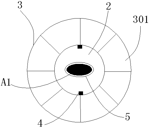
[0079] Such as figure 1 As shown, a new type of wire is sequentially composed of a load-bearing core, a conductor coating layer 2, and a conductor stranding layer 3 from inside to outside; the surface layer of the load-bearing core is provided with an anti-corrosion insulating layer 5.

[0080] The load-bearing core is a special-shaped load-bearing core A1; the effective diameter of the load-bearing core A1 is 1-25 mm; the cross-section of the special-shaped load-bearing core is square, rectangular, oval, flat or polygonal.

[0081] The thickness of the conductor coating layer 2 is ≥0.2mm, and the filling factor of the conductor coating layer is ≥94%; the conductor coating layer is aluminum, aluminum alloy, copper or copper alloy coating layer, and the conductor coating layer is one layer or Multi-layer; position calibration 4 is provided on the conductor cladding layer. The position calibration is to calibrate the orientation of the load-bearing core in the conductor claddin...

Embodiment 2

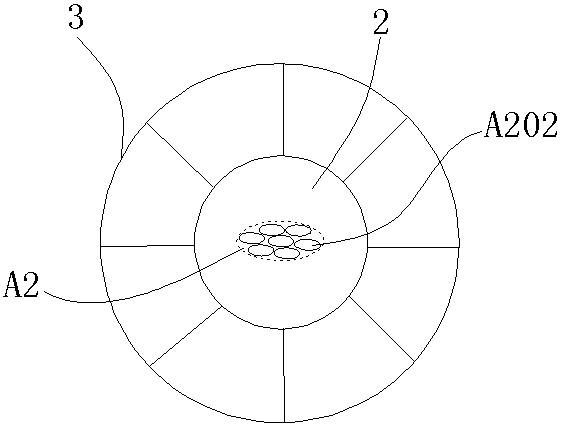
[0090] Such as figure 2 As shown, a new type of wire is sequentially composed of a load-bearing core, a conductor coating layer 2, and a conductor stranding layer 3 from inside to outside; the surface layer of the load-bearing core is provided with an anti-corrosion insulating layer 5.

[0091] The load-bearing core is a special-shaped load-bearing core group A2; the special-shaped load-bearing core group is composed of a plurality of special-shaped load-bearing cores arranged in a straight line or twisted, and the cross-section of the special-shaped load-bearing core group is non-circular.

[0092] The special-shaped force-bearing core group is composed of a plurality of special-shaped force-bearing mandrels A201; the diameter of the mandrels is 0.5-6mm.

[0093] In this embodiment, the diameter of the mandrel is 1-2 mm; the plurality of special-shaped load-bearing mandrels are arranged parallel to the wire axis to form a flat structure.

[0094] The thickness of the conduc...

Embodiment 3

[0104] Such as image 3 As shown, a new type of wire, from the inside to the outside is a different load-bearing core, a conductor cladding layer 2, and a conductor stranding layer 3; the load-bearing core is a carbon fiber flat wire A202 or a plurality of carbon fiber flat wires A202 Composition in a straight line.

[0105] In this implementation, the load-bearing core is composed of a plurality of flat carbon fiber wires A202 arranged in a straight line.


PUM

PropertyMeasurementUnit
Effective diameteraaaaaaaaaa
Thicknessaaaaaaaaaa
Thicknessaaaaaaaaaa

Abstract

The invention provides a novel wire and an application thereof. The novel wire comprises a force-bearing core, one or more conductor coating layers and a conductor twisting layer from inside to outside in sequence; the fore-bearing core is a special-shaped force-bearing core or special-shaped force-bearing core group; the special-shaped force-bearing core consists of a base material and reinforcefibers and is noncircular; each conductor coating layer is an aluminum, aluminum alloy, copper or copper alloy coating layer; and the conductor twisting layer is an aluminum, aluminum alloy, copper orcopper alloy wire which is wound around the conductor coating layer. By virtue of special structure, design and processing method, the shortcoming of the existing carbon fiber wire can be solved.

Description

technical field [0001] The patent of the invention belongs to the technical field of electric wire and cable used in the field of power transmission and distribution, and specifically relates to a new type of wire and its application. technical background [0002] With the rapid development of my country's economy, the obvious acceleration of urban modernization, the continuous expansion of urban scale and the rapid development of new rural construction, the demand for electricity has grown rapidly. Moreover, due to the imbalance in energy distribution and the development of the east and west, it is urgent to solve the bottleneck problem of high-power, long-distance energy transmission. Although the construction of ultra-high voltage has partially alleviated this contradiction, due to the limitation of the carrying capacity of traditional steel-reinforced aluminum stranded wires, transmission lines have been unable to withstand the rapid expansion of transmission capacity, a...

Claims


Application Information

Patent Timeline
IPC IPC(8): H01B7/02H01B7/18H01B7/28H01B7/36H01B9/00H01B13/00
CPCH01B7/1825H01B7/32H01B7/324H01B7/326H01B7/36H01B9/005Y02A30/14
Inventor 黄建平黄建中
Owner 深圳市圣龙新材料科技有限公司
Learn More