
Projection system

A projection system and color gamut technology, applied in the field of projection systems, can solve the problem that the projection system cannot display a specific color gamut, achieve good display effect, widen the color gamut, and improve the effect of picture color distortion

Active Publication Date: 2018-07-13
APPOTRONICS CORP LTD
View PDF16 Cites 17 Cited by
  • Summary
  • Abstract
  • Description
  • Claims
  • Application Information

AI Technical Summary

Problems solved by technology

[0005] In order to solve the technical problem that the prior art projection system cannot display a specific color gamut, the present invention provides a projection system that can effectively widen the color gamut

Method used


Image

  • Projection system
  • Projection system
  • Projection system

Examples


no. 1 approach

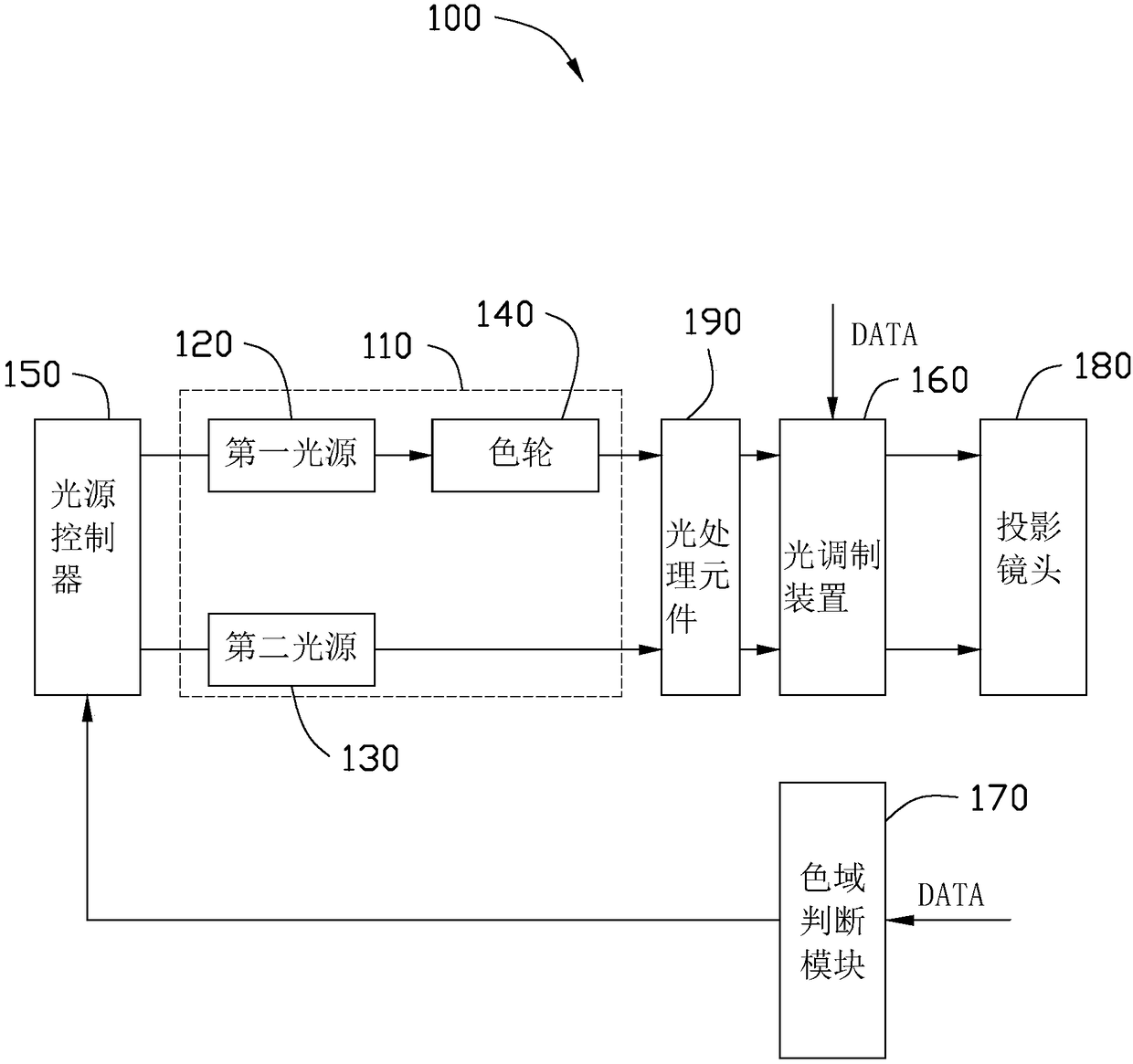
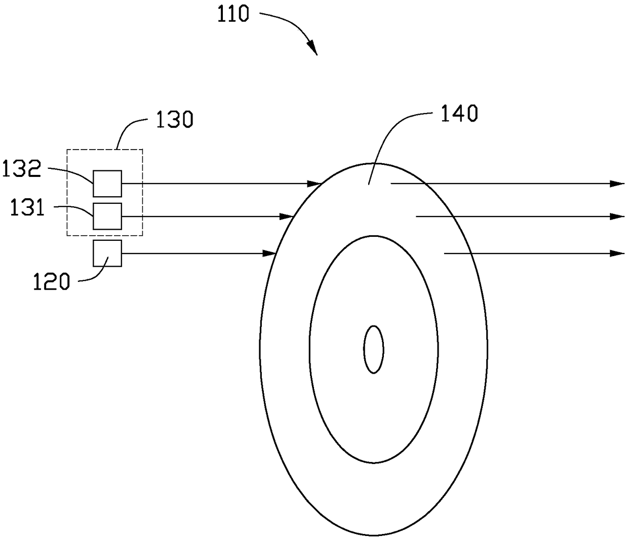
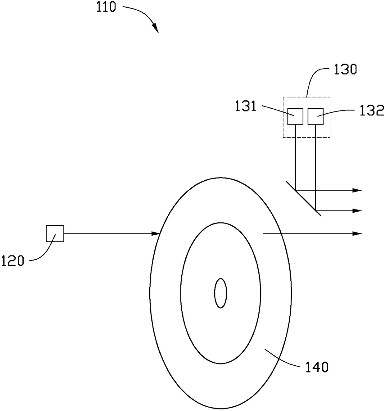
[0043] see figure 1 , figure 1 is a schematic structural diagram of the projection system 100 according to the first embodiment of the present invention. The projection system 100 includes a light emitting device 110 , a light source controller 150 , a light processing element 190 , a light modulation device 160 , a color gamut judgment module 170 , and a projection lens 180 . The light emitting device 110 includes a first light source 120 , a second light source 130 and a color wheel 140 .

[0044] The first light source 120 is used to emit primary color light, the primary color light is used to modulate images, and the primary color light can be used to modulate images within the first color gamut. The color wheel 140 is located on the optical path where the primary color light emitted by the first light source 120 is located. The color wheel 140 includes at least two segmented areas, and the at least two segmented areas receive the primary color light and emit correspondi...

no. 2 approach

[0071] see Figure 7 , Figure 8 , Figure 7 is a schematic block diagram of the projection system 200 according to the second embodiment of the present invention, Figure 8 It is a schematic structural diagram of the color wheel 240 of the projection system 200 according to the second embodiment of the present invention. The projection system of the second embodiment is similar to the projection system of the first embodiment, that is to say, most of the above descriptions for the first embodiment can basically be applied to the second embodiment, the difference between the two The main reasons are: the structure of the color wheel 240 , the number of spatial light modulators in the light modulation device, and the driving timing of the light source and the spatial light modulators are different. It can be understood that the following description will mainly focus on the parts that are different from the second embodiment and the first embodiment, and the same parts betwe...


PUM


Abstract

Disclosed is a projection system. The projection system comprises a first light source, a second light source, a color gamut judgment module, a light source controller and a light modulation apparatus; the first light source is used for giving out primary light for modulating an image; the primary light can be used for modulating an image within a first color gamut range; the second light source is used for giving out supplementing light for expanding the color gamut of at least one kind of light from the primary light emitted from the first light source; the color gamut judgment module is used for receiving image data and judging a color gamut range of a to-be-displayed image according to the image data, and outputting a control signal according to the color gamut range; the light sourcecontroller is used for receiving the control signal and controlling the starting and closing of the first light source and the second light source according to the control signal to enable the color gamut range which can be modulated by the light emitted from the first light source and the second light source to satisfy the color gamut range of the to-be-displayed image; and the light modulation apparatus is used for performing image modulation on the primary light and the supplementing light to generate projection light needed by the to-be-displayed image.

Description

technical field [0001] The present invention relates to the field of projection technology, in particular to a projection system. Background technique [0002] Existing projection systems are widely used in theaters, education, television and other fields. Projection systems can be divided into DMD (Digital Micromirror Device), LCOS (Liquid Crystal on Silicon), and LCD (Liquid Crystal Display) according to the type of light modulation device used. etc. According to the number of light modulation devices, it can be divided into single-chip, double-chip and three-chip systems. In terms of light sources for projection systems, traditional light sources include bulb light sources such as UHP and xenon lamps. At present, LED light sources, RGB pure laser light sources, and laser-excited phosphor light sources are gradually developed. The latter can be considered to be based on semiconductor light-emitting devices. light source. Limited by the etendue, the projection system of t...

Claims


Application Information

Patent Timeline
Patent Type & Authority Applications(China)
IPC IPC(8): G03B21/20
CPCG03B21/2013G03B21/204G03B21/206G03B21/20
Inventor 胡飞郭祖强李屹
Owner APPOTRONICS CORP LTD
Learn More