Urban waste cyclone combustion system and coupled coal-fired power plant generating system and method thereof
A cyclone combustion, coal-fired power station technology, applied in the combustion method, combustion type, combined combustion mitigation and other directions, to achieve the effects of reducing pollution, high degree of harmless treatment, and high efficiency utilization
- Summary
- Abstract
- Description
- Claims
- Application Information
AI Technical Summary
Problems solved by technology
Method used
Image
Examples
Embodiment 1
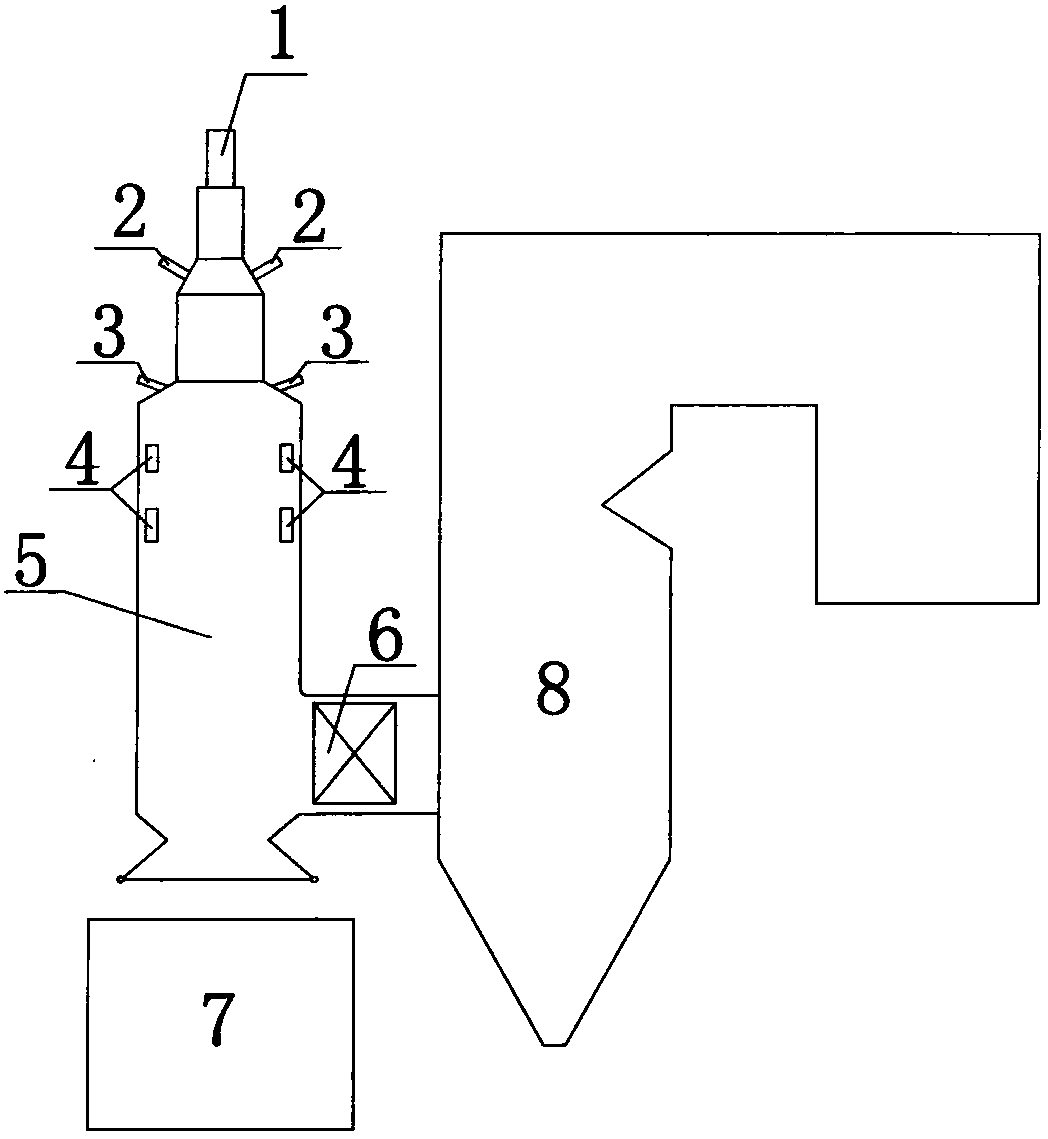
[0039] figure 1 It is a schematic diagram of a municipal solid waste cyclone combustion system that adopts cyclone combustion to co-burn municipal solid waste. The municipal solid waste cyclone combustion system includes a coal-fired boiler 8 and a cyclone furnace 5, and the cyclone furnace 5 is connected to the coal-fired boiler 8 through a flue.
[0040]The top of cyclone furnace 5 is provided with waste fuel inlet 1, and the surrounding wall of cyclone furnace 5 is provided with hot air inlet 2, pulverized coal primary air inlet 3, and secondary air inlet 4 successively from top to bottom. The lower part of the garbage fuel inlet 1 and the upper part of the hot air inlet 2 are equipped with guide blades. The lower part of the cyclone furnace 5 is provided with a flue gas outlet, and the flue gas outlet is connected to the coal-fired boiler 8 through a flue, and a slag collection tube bundle 6 is arranged in the flue connecting the cyclone furnace 5 and the coal-fired boiler...
Embodiment 2
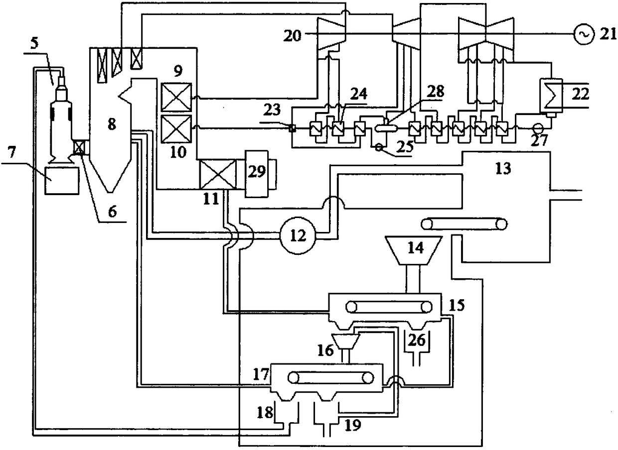
[0047] figure 2 It is a schematic diagram of the municipal solid waste cyclone combustion coupled coal-fired power station power generation system formed by the municipal solid waste cyclone combustion system coupled with the coal-fired power station described in Example 1. The municipal solid waste cyclone combustion coupled coal-fired power station power generation system includes the embodiment 1 In the municipal solid waste cyclone combustion system described above, the coal-fired boiler 8 is connected to the outlet of the fan 12 and the exhaust gas outlet of the secondary garbage screening system 17 through pipelines, and the inlet of the fan 12 is connected to the garbage storage bin 13 to ensure the negative pressure of the garbage storage bin 13. Prevent the garbage smell from spreading outward and affecting the environment. A low-temperature reheater 9, an economizer 10, an air preheater 11, and a flue gas treatment device 29 are sequentially arranged in the tail flu...
PUM
 Abstract
Description
Claims
Application Information
 - R&D
- Intellectual Property
- Life Sciences
- Materials
- Tech Scout
- Unparalleled Data Quality
- Higher Quality Content
- 60% Fewer Hallucinations
Browse by: Latest US Patents, China's latest patents, Technical Efficacy Thesaurus, Application Domain, Technology Topic, Popular Technical Reports.
© 2025 PatSnap. All rights reserved.Legal|Privacy policy|Modern Slavery Act Transparency Statement|Sitemap|About US| Contact US: help@patsnap.com


