
High-pier steel girder pushing supporting device and construction method

A technology of supporting devices and steel girders, which is applied in bridges, bridge materials, bridge construction, etc., can solve the problems of high safety risk of the main structure, large structure consumption, and large construction period, so as to save manpower and material resources, uniform force transmission, and The effect of short construction period

Pending Publication Date: 2018-07-10
CHINA RAILWAY CONSTR BRIDGE ENG BUREAU GRP NO 4 ENG +1
View PDF6 Cites 0 Cited by
  • Summary
  • Abstract
  • Description
  • Claims
  • Application Information

AI Technical Summary

Problems solved by technology

[0004] In order to solve the problems of high safety risk of the main structure during the construction process, large amount of temporary structure, large construction period for installation and dismantling, and poor safety, the present invention provides a high pier steel beam jacking support device and construction method

Method used


Image

  • High-pier steel girder pushing supporting device and construction method
  • High-pier steel girder pushing supporting device and construction method
  • High-pier steel girder pushing supporting device and construction method

Examples


specific Embodiment approach 1

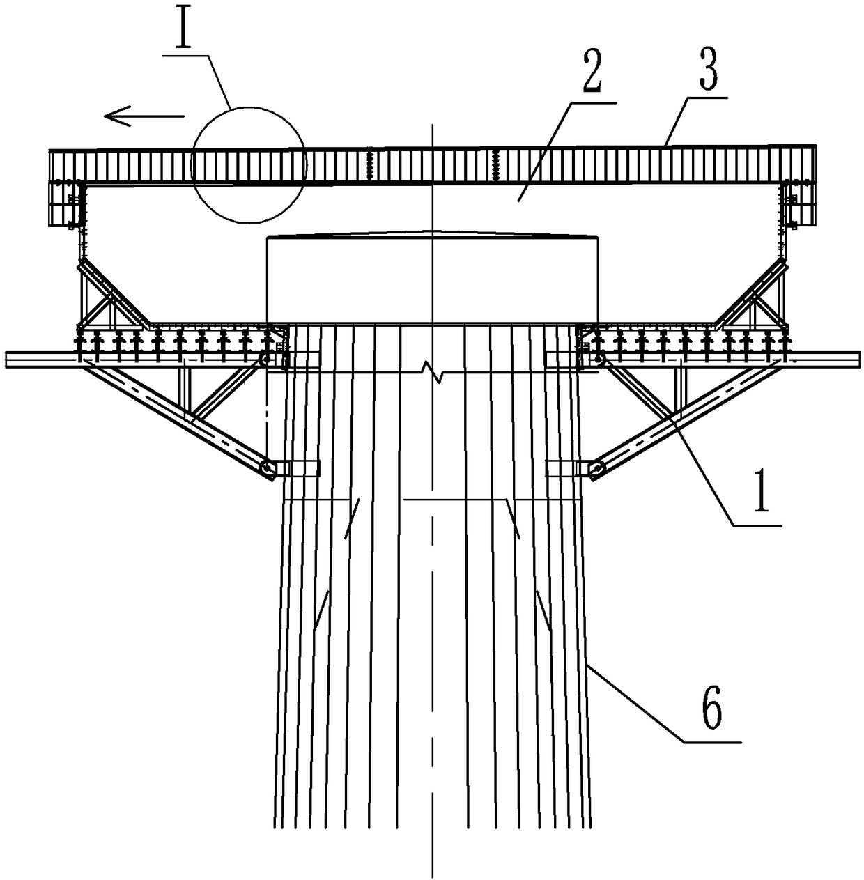
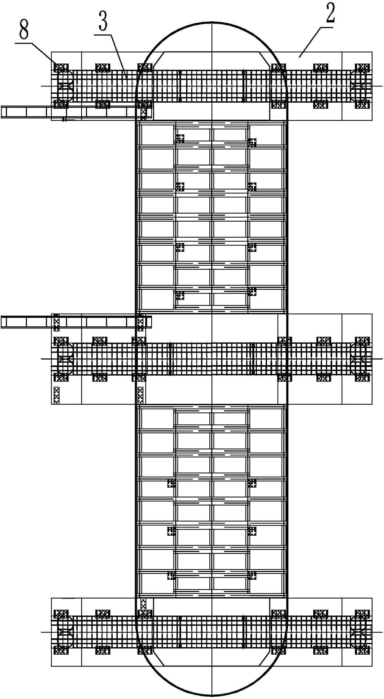
[0026] Specific implementation mode 1: Combination figure 1 with image 3 To illustrate this embodiment, this embodiment includes three concrete joists 2 and three steel slide beams 3;

[0027] Above the pier column 6, there are three parallel and evenly spaced concrete joists 2. The pier column 6 and each concrete joist 2 are connected by a plurality of pier cap steel bars 9, and each concrete joist 2 is provided with a steel skeleton inside. Reinforcing steel meshes 7 are arranged in the reinforcing steel framework, and the reinforcing steel frameworks are fixed to the steel slide beam 3, and each reinforcing steel mesh 7 is fixed to each pier cap reinforcing steel 9 together.

[0028] In this embodiment, pier cap steel bars 9 are provided, and each steel mesh 7 is fixed to each pier cap steel bar 9 to enhance the connection strength between the joist and the pier column 6.

specific Embodiment approach 2

[0029] Specific implementation manner two: combination figure 1 To illustrate this embodiment, the concrete joist 2 in this embodiment is rectangular, the bottom of the two sides of the concrete joist 2 in the length direction is chamfered, and the bottom of the concrete joist 2 protruding from both sides of the pier 6 is provided with Bracket 1.

[0030] In this embodiment, the bracket 1 plays a supporting role when the concrete joist 2 is poured, and also serves as an operating platform.

[0031] The other composition and connection relationship are the same as in the first embodiment.

specific Embodiment approach 3

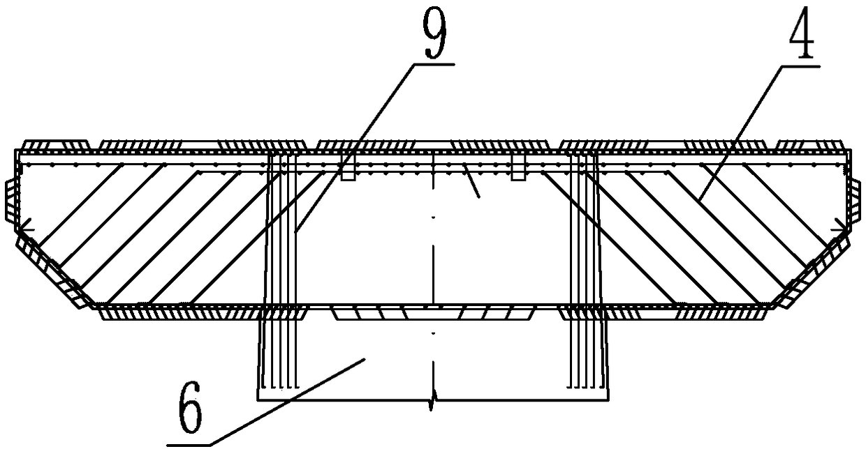
[0032] Specific implementation mode three: combination figure 1 with figure 2 To illustrate this embodiment, the shape of the reinforcement skeleton of the concrete joist 2 and the concrete joist 2 are the same, and the reinforcement skeleton of the concrete joist 2 is provided with oblique-stayed steel bars 4 connected to the reinforcement skeleton.

[0033] This embodiment improves the bending strength of both ends of the concrete joist 2.

[0034] The other composition and connection relationship are the same as in the second embodiment.


PUM


Abstract

The invention provides a high-pier steel girder pushing supporting device and a construction method and relates to the field of bridge engineering in order to solve problems of high safety risk, largetemporary structure usage, long working period of mounting and dismantling and poor safety of a main body structure in the construction process. The high-pier steel girder pushing supporting device comprises three concrete joists and three steel chute beams; the three parallel equally-spaced concrete joists are arranged above a pier column; the pier column and each concrete joist are connected with each other through a plurality of pier cap steel reinforcements; a steel reinforcement framework is arranged in each concrete joist; mesh reinforcements are arranged in the steel reinforcement frameworks; the steel reinforcement frameworks are fixedly connected with the steel chute beams; and each mesh reinforcement is fixedly connected with each pier cap steel reinforcement. The high-pier steel girder pushing supporting device and the construction method are applicable to bridge construction.

Description

Technical field [0001] The invention relates to the field of bridge engineering, in particular to a high pier steel beam push support device and a construction method. Background technique [0002] In the construction of large-span high-pier steel truss girder pushing, usually the reaction force of the nodes in the range of the pier top is relatively large. Due to the higher pier body, the eccentric bending moment of the pier body is large. The farther the reaction point is from the center line of the pier, the greater the eccentric bending moment. The traditional method of steel truss girder push construction adopts drag push. In addition, it is necessary to set up floor supports or pre-embedded brackets beside the pier on both sides of the pier to increase the longitudinal width of the pier and meet the requirement of pushing one inter-node of the steel beam. It is more difficult for high piers to erect floor supports, especially in construction areas with complex hydrogeologi...

Claims


Application Information

Patent Timeline
Patent Type & Authority Applications(China)
IPC IPC(8): E01D21/06E01D101/26
CPCE01D21/06E01D2101/26
Inventor 赵耀王宏毅林再志宁浩杰黄群广尤春颖王刚
Owner CHINA RAILWAY CONSTR BRIDGE ENG BUREAU GRP NO 4 ENG
Learn More