
Quick calculation method for auxiliary surface deformation position posture based on strain of antenna supporting leg

A technology for fast calculation and deformation position, applied in the direction of antenna support/installation device, antenna, calculation, etc.

Active Publication Date: 2018-07-06
XIDIAN UNIV
View PDF5 Cites 1 Cited by
  • Summary
  • Abstract
  • Description
  • Claims
  • Application Information

AI Technical Summary

Problems solved by technology

[0006] In order to solve the above-mentioned defects existing in the prior art, the object of the present invention is to provide a method for quickly calculating the deformation position and posture of the secondary surface based on the strain of the antenna support leg. In this way, the displacement of the connection point between the antenna support leg and the secondary surface can be quickly and effectively calculated, and then the position and attitude of the secondary surface after deformation can be obtained, which is conducive to the dual-reflector antenna meeting the electrical performance index requirements and making the antenna work performance optimal.

Method used


Image

  • Quick calculation method for auxiliary surface deformation position posture based on strain of antenna supporting leg
  • Quick calculation method for auxiliary surface deformation position posture based on strain of antenna supporting leg
  • Quick calculation method for auxiliary surface deformation position posture based on strain of antenna supporting leg

Examples


Embodiment Construction

[0063] The present invention will be further described in detail below in conjunction with the accompanying drawings and embodiments, but it is not used as a basis for any limitation of the present invention.

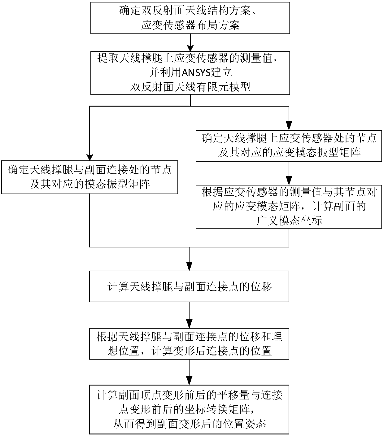
[0064] refer to figure 1 , the present invention is a fast calculation method for the deformation position and attitude of the secondary surface based on the strain of the antenna leg, and the specific steps are as follows:

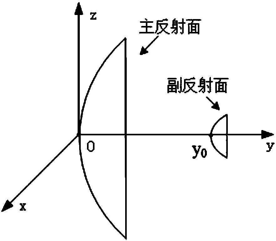
[0065] Step 1, determine the structure scheme of the double-reflector antenna and the layout scheme of the strain sensor.

[0066] Determine the structural parameters of the double-reflector antenna, including the diameter of the reflector, the arrangement of the structural units of the panel and the legs; the material properties of the double-reflector antenna include the density and elastic modulus of the main surface, the secondary surface, the legs and the back frame material , Poisson's ratio, etc. And determine the location and number n of ...


PUM


Abstract

The invention discloses a quick calculation method for an auxiliary surface deformation position posture based on the strain of an antenna supporting leg. The method comprises the steps that structural parameters, working frequencies and material attributes of a main surface, an auxiliary surface, the supporting leg and a back rack of a double-reflection-surface antenna and the distribution positions and number of strain sensors are determined; measurement values of the strain sensors on the antenna supporting leg are extracted, and a finite element model is established; nodes of a junction ofthe antenna supporting leg and the auxiliary surface and corresponding modal vibration mode matrixes are determined; nodes at the strain sensors on the antenna supporting leg and corresponding strainmodal vibration mode matrixes are determined; generalized modal coordinates of the antenna auxiliary surface are calculated; displacement of a connection point of the antenna supporting leg and the auxiliary surface is calculated; the position of the deformed connection point of the antenna supporting leg and the auxiliary surface is calculated; the translation amount of a vertex of the auxiliarysurface before and after deformation and a coordinate conversion matrix before and after deformation of the connection point are calculated, and the position posture after deformation of the auxiliary surface is obtained. According to the quick calculation method, displacement of the connection point of the antenna supporting leg and the auxiliary surface can be quickly and effectively calculated, and the method helps to meet the index requirement of electric performance of the double-reflection-surface antenna.

Description

technical field [0001] The invention belongs to the technical field of antennas, and in particular relates to a method for quickly calculating the deformation position and attitude of a secondary surface based on the strain of antenna support legs. Background technique [0002] As large antennas are widely used in astronomical observation, satellite tracking and communication, etc., the diameter and frequency band of dual-reflector antennas are also increasing, which brings many challenges to the structural design of the antenna and affects the electrical performance of the antenna. The requirements are also getting higher and higher. [0003] Due to the long-term exposure of the double-reflector antenna to the natural environment, its legs are easily affected by its own weight and environmental factors such as wind, rain, snow, and sunlight. These will cause strain on the antenna legs, resulting in changes in the position and attitude of the secondary reflector. Changes, t...

Claims


Application Information

Patent Timeline
IPC IPC(8): G06F17/50H01Q19/19H01Q1/12
CPCG06F30/23H01Q1/12H01Q19/19
Inventor 王从思李海华陈元魁应康王猛许谦王伟连培园张洁李申杜敬利
Owner XIDIAN UNIV
Learn More