
Hot blast furnace device for blast furnace iron making

A blast furnace ironmaking and hot blast stove technology, applied in blast furnaces, blast furnace details, blast furnace parts, etc., can solve the problems of reduced burner life, low production hot air efficiency, high burner gas density, etc., and achieve high production hot air efficiency , saving heat storage time, long burner life

Active Publication Date: 2018-07-06
ANHUI UNIVERSITY OF TECHNOLOGY AND SCIENCE
View PDF3 Cites 1 Cited by
  • Summary
  • Abstract
  • Description
  • Claims
  • Application Information

AI Technical Summary

Problems solved by technology

[0004] (1) A gas pipe and a combustion-supporting air pipe are installed on the furnace wall of the existing top-fired hot blast stove. When the air is fed together, because the air is on different sides, the gas and air are likely to mix unevenly after the air is taken in. As a result, some burners have large flames, and some burners have small flames. The life of burners with large flames will be greatly reduced, and because the gas density of the burners at the gas inlet is high, the burners near the gas inlet will spray The flame is large and easily damaged;
[0005] (2) Most of the existing top-burning hot blast stoves are vertically installed burners on the inner wall of the furnace wall to burn gas and transfer heat to the regenerator. Due to the small number of burners and the small combustion area, the combustion heat The speed and temperature are greatly reduced, the heat storage body is heated slowly, and the heat received by the vault and the heat storage body is almost equal, and the life of the vault is not long;
[0006] (3) Most of the regenerators in current hot blast stoves use checker bricks to store heat, but since the direct contact area between the checker bricks and the heat generated by the burner is only the top surface, the heat transfer efficiency is low and the regenerators are heated slowly , when the temperature of the regenerator is sufficient, the heating of the cold air will also slow down, and the efficiency of producing hot air will become lower

Method used


Image

  • Hot blast furnace device for blast furnace iron making
  • Hot blast furnace device for blast furnace iron making

Examples


Embodiment

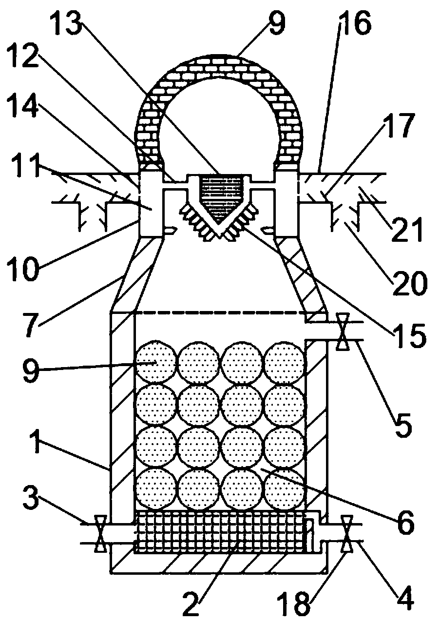
[0025] Such as figure 1 As shown, the present invention provides a hot blast stove device for blast furnace ironmaking, comprising a furnace body 1, a furnace grate 2 is installed at the bottom of the inner wall of the furnace body 1, and a cold air pipe 3 is fixedly installed at the bottom of the side wall of the furnace body 1 And the waste gas pipe 4, the top of the side wall of the furnace body 1 is fixedly equipped with a hot air pipe 5, the cold wind pipe 3 and the waste gas pipe 4 are parallel and both are symmetrical about the center of the furnace body 1, so that the cold wind pipe 3 enters the cold wind and the waste gas pipe The 4 rows of exhaust gas do not interfere with each other, and the efficiency is higher. The furnace grate 2 is located between the cold air pipe 3 and the exhaust gas pipe 4. The furnace grate 2 has two functions here. First, it makes the cold air entering from the cold air pipe 3 Evenly spread to the regenerator 6, so that the cold air is hea...


PUM


Abstract

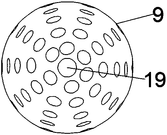
The invention discloses a hot blast furnace device for blast furnace iron making. The hot blast furnace device for blast furnace iron making comprises a furnace body. A fire grate is arranged at the bottom of the inner wall of the furnace body. A cold air pipe, a waste gas pipe and a hot air pipe are arranged on the side wall of the furnace body. A heat accumulation chamber is arranged in the middle of the furnace body. The top of the furnace body is connected with a vault through a connecting body. The heat accumulation chamber is internally filled with heat accumulation balls. The connectingbody comprises an annular wall. The inner wall of the annular wall is connected with a spraying burner through a connecting pipe. The outer wall of the annular wall is evenly provided with three-waypipes through gas ports. A plurality of nozzles are fixedly arranged on the side face of the spraying burner and the inner wall of the annular wall. A plurality of air deflectors are arranged on the inner walls of the three-way pipes. Gas is evenly scattered into the various nozzles through the three three-way pipes and the air deflectors, and the service life of the nozzles is longer. The spraying burner and the nozzles arranged on the annular wall are used for jointly spraying fire, the heat of the heat accumulation chamber is rapidly increased, and the heat accumulation time is saved. The nozzles downwards obliquely spray fire, the service life of the vault is longer, the heat accumulating balls are adopted in the heat accumulating chamber for heat accumulation, the heat accumulating efficiency is high, and hot air generation is faster.

Description

technical field [0001] The invention relates to the technical field of hot blast stoves, in particular to a hot blast stove device for blast furnace ironmaking. Background technique [0002] The hot blast stove is a device for heating and blasting the blast furnace, and it is an indispensable and important part of the modern blast furnace. The most commonly used modern large blast furnace is the regenerative checker brick hot blast stove. The regenerative hot blast stove can be divided into top combustion type, internal combustion type and external combustion type according to the combustion method. Due to the good performance and high heat conduction efficiency of top-fired hot blast stoves, top-fired hot blast stoves are now the most popular in large-scale blast furnace ironworks. [0003] The existing ones have the following deficiencies and problems: [0004] (1) A gas pipe and a combustion-supporting air pipe are installed on the furnace wall of the existing top-fired...

Claims


Application Information

Patent Timeline
Patent Type & Authority Applications(China)
IPC IPC(8): C21B9/00
CPCC21B9/00
Inventor 杨国太李飞张小龙苗润泽
Owner ANHUI UNIVERSITY OF TECHNOLOGY AND SCIENCE
Learn More