
Improved visual trachea cannula

A technology of tracheal intubation and intubation, which is applied in the field of medical devices, can solve the problems of time-consuming operation, increased workload of physicians, and great human injury, so as to reduce the difficulty and complexity of operation, easy and fast insertion operation, and reduce the pain of treatment Effect

Pending Publication Date: 2018-07-06
ZHEJIANG UE MEDICAL
View PDF11 Cites 6 Cited by
  • Summary
  • Abstract
  • Description
  • Claims
  • Application Information

AI Technical Summary

Problems solved by technology

[0002] Endotracheal intubation is an important method often used in general anesthesia, cardiopulmonary resuscitation, and rescue of critically ill patients with respiratory dysfunction. The success rate of difficult airway intubation. The use of ordinary tracheal intubation requires the use of intubation light sticks or laryngoscopes and other medical instruments. , the laryngoscope and the light rod do great damage to the human body, and cannot achieve the visualization effect, and the visual laryngoscope can only observe the oral cavity and the glottis, and cannot fully achieve the visual effect, and the operation is time-consuming and costly; therefore, providing A visual tracheal intubation tube with precise and fast operation, safe and effective use, little damage to human tissue, and dynamic video monitoring during the whole process is very necessary
[0003] CN205683368U discloses a visual tracheal intubation, in which a camera is arranged on the front end of the arc-shaped tube body. In current medical treatment, intubation guides made of soft materials are generally used to avoid trauma to the patient during the intubation process, but Installing a camera on the front end makes the socket hard, which weakens or even eliminates the advantages of a soft socket, making it difficult to popularize; at the same time, secretions from the oral cavity and esophagus will inevitably contaminate the camera during intubation, making it difficult to achieve a visual effect

Method used


Image

  • Improved visual trachea cannula
  • Improved visual trachea cannula
  • Improved visual trachea cannula

Examples


Embodiment 1

[0026] Embodiment 1 Visible endotracheal intubation 1

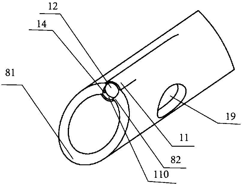
[0027] Such as figure 1 with image 3 As shown, a visible tracheal intubation tube includes a tube body and a cuff, and the tube body includes a flexible patient end 1, a machine end 3 and a lumen 2 extending from the patient end 1 to the machine end. The cuff 4 is arranged on the flexible patient end 1, and the inner wall of the tube is provided with an inflatable channel, and the inflatable channel is connected with an inflatable head outside the tube, and the socket of the intubation tube is an oblique opening 8 (inclined opening). The end has a proximal end 82 and a distal end 81. Adjacent but not connected accommodating chambers 11 and flushing channels 13 are provided on the inner wall of the tube extending from the beveled proximal end 82 to the head of the lumen. The shape of the tube body can be varied. changes, such as figure 1 As shown, the lumen 2 is arc-shaped, and the arc-shaped official lumen has a relat...

Embodiment 2

[0032] Embodiment 2 Visible endotracheal intubation 2

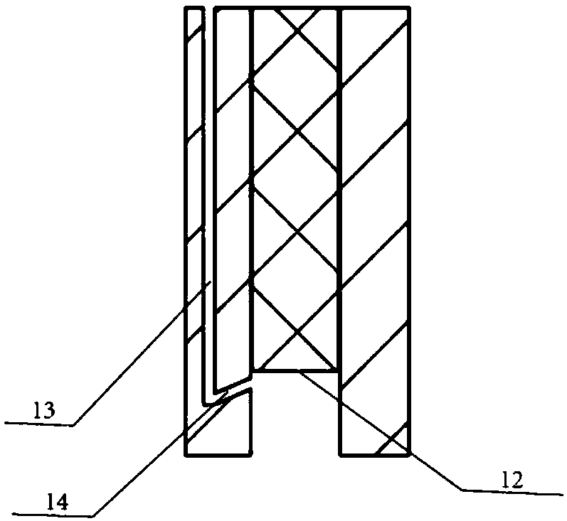
[0033] On the basis of Embodiment 1, this embodiment provides a function that can keep the camera clear at any time, such as image 3As shown, a sectional view of the patient end is shown. In order to flush the camera at the end, it is preferable that the flushing channel 13 is adjacent to the accommodating chamber 11. communicated, that is, they are separated from each other, and in the embodiment provided by the present invention, the lateral distance between the accommodating chamber and the inner wall of the flushing channel in the inner peripheral area of ​​the tube is 1-2mm, and the flushing channel 13 is close to the proximal end of the inclined port. The position is provided with a flushing hole 14 that is bent towards the camera 12 and communicated with the accommodating cavity 11. The flushing hole 14 is located at the end of the flushing channel 13 and is substantially flush with the camera 12. The substantiall...

Embodiment 3

[0036] Embodiment 3 Visible endotracheal intubation 3

[0037] Such as Figure 4 As shown, this embodiment combines the tracheal intubation provided by Embodiment 1 and Embodiment 2, and at the same time, a spring 20 is placed around the inner wall 21 of the tracheal intubation to cooperate with the existing tracheal intubation to form a stronger endotracheal intubation. It can avoid the risk of gas not passing through due to twisting or bending, and it can also play a supporting role. In terms of materials, you can choose relatively soft materials, such as PVC, silicone and other materials.


PUM


Abstract

The invention provides a visual trachea cannula. The cannula comprises a cannula body and a cuff. The cannula body comprises a flexible patient end, a machine end and a cannula cavity extended from the patient end to the machine end. The cuff is installed at the flexible patient end, and connected with an inflating device. The cannula body is provided with a bevel opening. The inner wall of the cannula body extended along the near end of the bevel opening is provided with an accommodating cavity and a washing channel. The opening end of the accommodating cavity is aligned to the near end of the bevel opening. The washing channel is adjacent to and separated from the accommodating cavity. A camera device is installed in the accommodating cavity. The camera device is inwards retracted relative to the near end of the bevel opening. The washing channel is provided with a washing hole which faces to the camera device and is communicated with the accommodating cavity. The flexible advantageof the flexible patient end is reserved, and the visual effect is achieved. In addition, the effect of cleaning a camera is remarkable.

Description

technical field [0001] The invention belongs to the technical field of medical devices, and in particular relates to an improved visible tracheal intubation tube. Background technique [0002] Endotracheal intubation is an important method often used in general anesthesia, cardiopulmonary resuscitation, and rescue of critically ill patients with respiratory dysfunction. The success rate of difficult airway intubation. The use of ordinary tracheal intubation requires the use of intubation light sticks or laryngoscopes and other medical instruments. , the laryngoscope and the light rod do great damage to the human body, and cannot achieve the visualization effect, and the visual laryngoscope can only observe the oral cavity and the glottis, and cannot fully achieve the visual effect, and the operation is time-consuming and costly; therefore, providing A visual tracheal intubation tube that is accurate and fast in operation, safe and effective in use, has little damage to huma...

Claims


Application Information

Patent Timeline
Patent Type & Authority Applications(China)
IPC IPC(8): A61M16/04A61B1/267A61B1/012A61B1/04
CPCA61M16/04A61B1/012A61B1/04A61B1/267A61M2210/1032A61M2210/005
Inventor 左明章薛富善王卫东李宏博张升炎朱福斌李芳柄
Owner ZHEJIANG UE MEDICAL
Learn More