
Intelligent tool creating and using method for three-dimensional software

A 3D software and cutting tool technology, applied in the field of mechanical processing, can solve problems such as ignorance of conditions and parameters, difficult standardization of cutting parameters, and low efficiency of engineer design process, so as to improve design efficiency and reduce error rate.

Inactive Publication Date: 2018-06-29
SUZHOU ERIC MECHANICS & ELECTRONICS CO LTD
View PDF7 Cites 6 Cited by
  • Summary
  • Abstract
  • Description
  • Claims
  • Application Information

AI Technical Summary

Problems solved by technology

[0002] In product design, 3D software is usually used for modeling. After the product is formed, the corresponding processing technology needs to be designed according to the structure of the product. The existing 3D software has the function of creating tools in terms of technology, and tools are usually selected through this function. In the process of processing, when using the same tool for different products, it needs to be repeatedly created, and the cutting parameters for processing must be reset every time; some new engineers do not understand the machine tools and tools within the company when designing When creating a cutting tool, it is necessary to repeatedly confirm the selected machine tool and whether the cutting tool is equipped, resulting in low efficiency of the engineer's design process, which is inconvenient for the management and use of the cutting tool in the enterprise, and the cutting parameters selected by each engineer in the enterprise Difficult to standardize

Method used


Image

  • Intelligent tool creating and using method for three-dimensional software
  • Intelligent tool creating and using method for three-dimensional software
  • Intelligent tool creating and using method for three-dimensional software

Examples


Embodiment Construction

[0021] The present invention will be described in detail below in conjunction with the accompanying drawings.

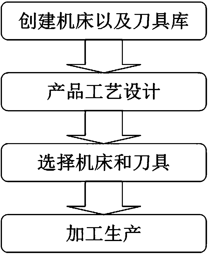
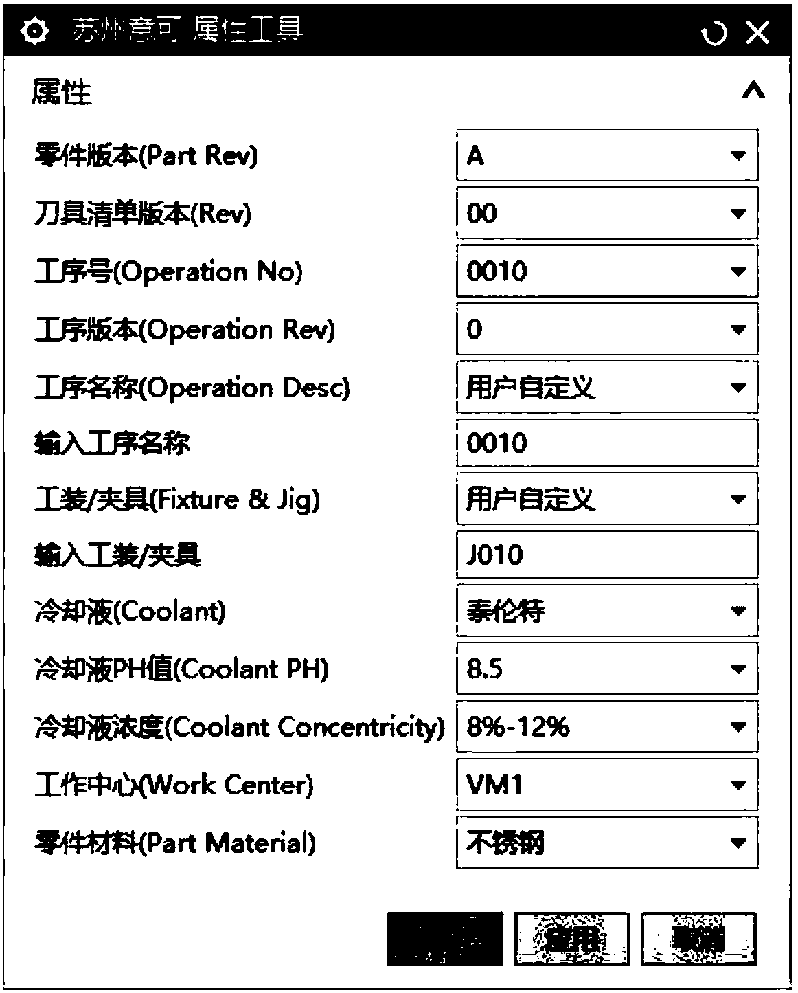
[0022] Such as figure 1 A method for creating and using an intelligent tool for 3D software is shown, and the steps of the method are as follows:

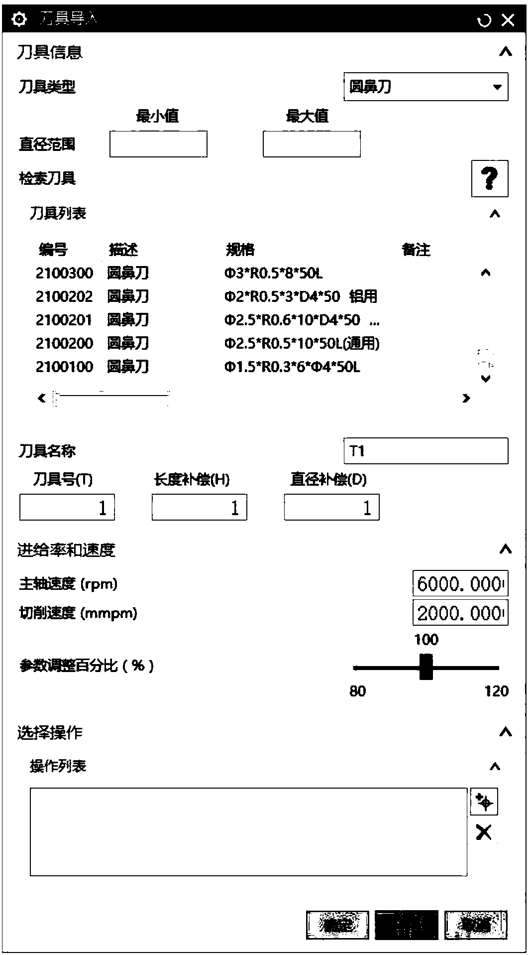
[0023] S1. Create a machine tool and tool library. According to the machine tools and tools already equipped by the enterprise, summarize the parameters of the machine tools and tools and form a form, and import the form into the 3D software; there are two main methods. The first is through the 3D software. The tool creation function in the enterprise can enter the information of the machine tools and cutting tools that the enterprise has already equipped into the 3D software for backup, so as to prepare for later selection; the second method is to enter the information of the machine tools and cutting tools into the form through the designed standard form, and then use the 3D The software imports the form into it for la...


PUM


Abstract

The invention relates to an intelligent tool creating and using method for three-dimensional software. The method includes steps: S1, machine tool and tool library creation, to be more specific, collecting machine tool and tool parameters to form a form, and importing the form into the three-dimensional software; S2, product process design, to be more specific, designing product machining processes by product engineers according to product specific parameters, and importing into the three-dimensional software; S3, machine tool and tool selection, namely selecting appropriate machine tools andtools for each procedure in the three-dimensional software; S4, machining production, to be more specific, transmitting selected machining processes to a production center. The uniform machine tool and tool library and a cutting parameter database are created, and the machine tools and tools of enterprises are selected without repeated confirmation and repeated creation of tools; by an automatic screening function, cutting parameters can be selected automatically and reasonably according to different materials and different machine tools, and design efficiency of the engineers is improved; anautomatically created tool list provides tool mounting guidance for a machining center.

Description

technical field [0001] The invention relates to software application in the field of mechanical processing, in particular to a method for creating and using an intelligent tool for three-dimensional software. Background technique [0002] In product design, 3D software is usually used for modeling. After the product is formed, the corresponding processing technology needs to be designed according to the structure of the product. The existing 3D software has the function of creating tools in terms of technology. Usually, the tool is selected through this function. In the process of processing, when different products use the same tool, they need to be created repeatedly, and the cutting parameters for processing must be reset every time; some new engineers do not understand the machine tools and tools inside the company when designing When creating a cutting tool, it is necessary to repeatedly confirm the selected machine tool and whether the cutting tool is equipped, resulti...

Claims


Application Information

Patent Timeline
Patent Type & Authority Applications(China)
IPC IPC(8): G06F17/50
CPCG06F30/17G06F30/20
Inventor 常赟胡磊
Owner SUZHOU ERIC MECHANICS & ELECTRONICS CO LTD
Learn More