
Laser additive and subtractive composite manufacturing device and method

A manufacturing device and laser additive technology, applied in manufacturing tools, additive manufacturing, additive processing, etc., can solve problems such as affecting additive, high scrap rate, and difficulty in meeting, and achieve improved product quality, improved additive quality, The effect of reducing the scrap rate

Inactive Publication Date: 2018-06-29
NANJING HUIRUI PHOTOELECTRIC TECH CO LTD
View PDF13 Cites 30 Cited by
  • Summary
  • Abstract
  • Description
  • Claims
  • Application Information

AI Technical Summary

Problems solved by technology

[0002] With the continuous and in-depth application of laser technology, laser metal additive technology is already a relatively mature technology in the world, which can realize the manufacture of more complex parts. However, the surface accuracy of additive materials is insufficient, and traditional machine addition and subtraction are required. When the inner side of some complex curved surface has higher precision requirements, after the completion of material addition, the tool space for machine addition and subtraction is limited and difficult to achieve, and the high-precision requirements of the inner surface cannot be realized. Therefore, it is necessary to Subtract part of the material processing, and then continue to add material manufacturing; at the same time, for some additive positions, the traditional three-axis linkage is difficult to meet, and special curved surfaces are difficult to achieve
[0003] Moreover, during the laser additive process, due to fluctuations in laser and carrier gas powder feeding, especially in the fine additive process, local collapse and loss will occur, affecting the quality of the additive material, and the scrap rate is high; in the material reduction process , due to the material and processing method, there may be deformation caused by processing, which will affect the subsequent addition

Method used


Image

  • Laser additive and subtractive composite manufacturing device and method
  • Laser additive and subtractive composite manufacturing device and method

Examples


Embodiment Construction

[0035] The present invention will be described in further detail below in conjunction with specific embodiments.

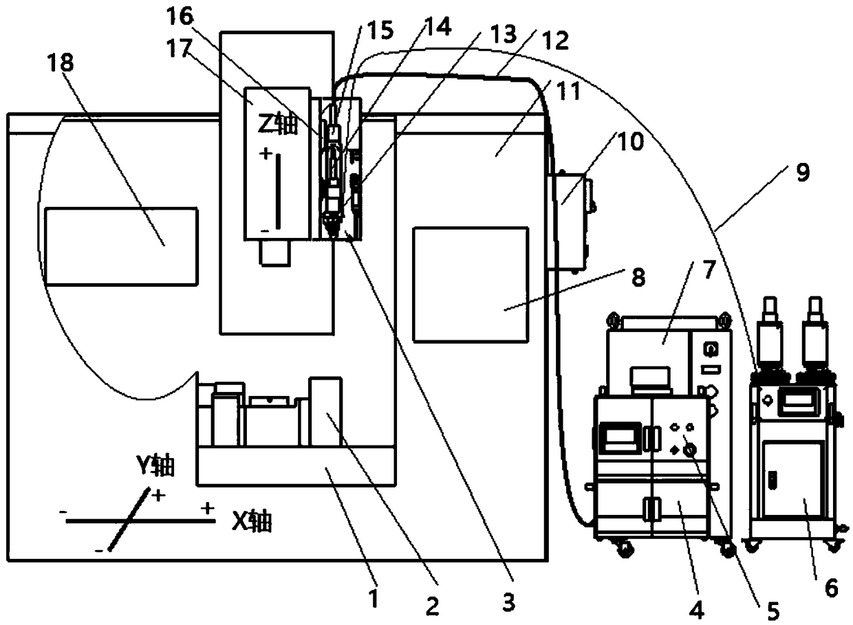
[0036] A laser additive and subtractive composite manufacturing device, including a material subtractive system, a laser additive system and a control system; the material subtractive system is a five-axis linkage machine tool, including a bed body 11, an X / Y axis motion mechanism 1, an A / B A two-axis positioner 2 and a Z-axis motion mechanism 17; a gripper is installed on the X / Y-axis motion mechanism 1 for clamping substrates; the X / Y-axis motion mechanism 1 is located on the bed The lower part of the body 11, on which the X / Y-axis motion mechanism 1 is installed; the Z-axis motion mechanism 17 is located above the X / Y-axis motion mechanism 1, and is installed on the upper part of the bed body 11; The laser additive system includes a laser device, a water cooling device and a powder device, the laser device includes a laser 4 and an optical head 15, the optical ...


PUM


Abstract

The invention discloses a laser additive and subtractive composite manufacturing device and method. The device comprises a subtractive system, a laser additive system, a control system and a monitoring system, wherein the subtractive system is a five-axis linkage machine tool, the laser additive system comprises a laser device, a water cooling device and a pulverizing device, the control system isconnected with the subtractive system and the laser additive system through signals, and the monitoring system is connected with the control system through signals and used for acquiring a weld poolimage and workpiece dimension parameters and transmitting the weld pool image and the workpiece dimension parameters to the control system. The manufacturing method is characterized in that additive and subtractive operations are performed by the aid of the device and repeated until processing is qualified. The method has the advantages of high yield, low running cost and the like.

Description

technical field [0001] The invention belongs to the technical field of fine processing and manufacturing, and in particular relates to a laser additive-subtractive composite manufacturing device and method. Background technique [0002] With the continuous and in-depth application of laser technology, laser metal additive technology is already a relatively mature technology in the world, which can realize the manufacture of more complex parts. However, the surface accuracy of additive materials is insufficient, and traditional machine addition and subtraction are required. When the inner side of some complex curved surface has higher precision requirements, after the completion of material addition, the tool space for machine addition and subtraction is limited and difficult to achieve, and the high-precision requirements of the inner surface cannot be realized. Therefore, it is necessary to Part of the material reduction process is followed by additive manufacturing; at the...

Claims


Application Information

Patent Timeline
IPC IPC(8): B22F3/105B23K26/38B33Y10/00B33Y30/00
CPCB23K26/38B33Y10/00B33Y30/00B22F10/00B22F12/90B22F10/25B22F10/32B22F10/50B22F12/20Y02P10/25
Inventor 齐欢黄斌彧杨波李先锋蔡国双
Owner NANJING HUIRUI PHOTOELECTRIC TECH CO LTD
Learn More