Cutting lubricating method directly acting on tool-scrap interface and cutting tool

A cutting tool and interface technology, applied in the direction of tools used in lathes, accessories of tool holders, manufacturing tools, etc., can solve the problems of short tool life, difficult for lubricant to enter the chip interface, environmental pollution, etc., and achieve lubrication effect. Good, shorten the cooldown time, optimize the effect of the cooling effect

Inactive Publication Date: 2018-06-22
QINGDAO UNIV OF SCI & TECH
View PDF6 Cites 0 Cited by
  • Summary
  • Abstract
  • Description
  • Claims
  • Application Information

AI Technical Summary

Problems solved by technology

[0003] The invention provides a cutting lubrication method directly acting on the knife-chip interface and a cutting tool, which solves the technical problems in the prior art that the lubricant is difficult to enter the knife-chip interface during cutting, the environment is seriously polluted, and the service life of the tool is short

Method used


Image

  • Cutting lubricating method directly acting on tool-scrap interface and cutting tool
  • Cutting lubricating method directly acting on tool-scrap interface and cutting tool
  • Cutting lubricating method directly acting on tool-scrap interface and cutting tool

Examples


Embodiment 1

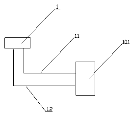
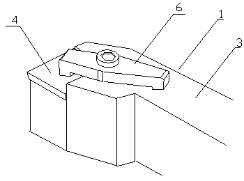
[0031] refer to figure 1 , figure 2 and image 3 , a cutting tool, the tool 1 includes a cutter body 4 and a cutter bar 3, the front end of the cutter bar 3 is provided with a knife groove 5 for placing the cutter body 4, the upper surface of the cutter bar 3 is provided with a threaded fastening hole, and the center of the pressure plate 6 is provided with an upper and lower Through the screw hole, the pressure plate 6 is screwed into the screw hole and the threaded fastening hole to connect with the knife rod 3 through the bolt. 4 close contact.

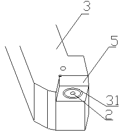
[0032] refer to figure 1 , Figure 4 and Figure 5, the cutter 1 is provided with a passage from the bottom surface to the cutter-chip interface. The passage includes the microchannel 2 within the range of the cutter body 4 and the upper and lower sections of the lubrication pipe 7 within the range of the cutter rod 3. When the cutter body 4 and the cutter rod 3 When connected, the lower opening of the microchannel 2 is conn...

Embodiment 2

[0037] refer to figure 1 , figure 2 and image 3 , a cutting tool, the tool 1 includes a cutter body 4 and a cutter bar 3, the front end of the cutter bar 3 is provided with a knife groove 5 for placing the cutter body 4, the upper surface of the cutter bar 3 is provided with a threaded fastening hole, and the center of the pressure plate 6 is provided with an upper and lower Through the screw hole, the pressure plate 6 is screwed into the screw hole and the threaded fastening hole to connect with the knife rod 3 through the bolt. 4 close contact.

[0038] refer to figure 1 , Figure 4 and Figure 5 , the cutter 1 is provided with a passage from the bottom surface to the cutter-chip interface. The passage includes the microchannel 2 within the range of the cutter body 4 and the upper and lower sections of the lubrication pipe 7 within the range of the cutter rod 3. When the cutter body 4 and the cutter rod When 3 is connected, the lower opening of the microchannel 2 is ...

Embodiment 3

[0043] refer to figure 1 , figure 2 and image 3 A cutting tool, the tool 1 includes a cutter body 4 and a cutter bar 3, the front end of the cutter bar 3 is provided with a knife groove 5 for placing the cutter body 4, the upper surface of the cutter bar 3 is provided with a threaded fastening hole, and the center of the pressure plate 6 is provided with a vertical connection The screw hole, the pressing plate 6 is screwed into the screw hole and the threaded fastening hole to be connected with the knife bar 3 by bolts, when the pressing plate 6 is fixed on the knife bar 3 by the bolt, the bottom surface of one end of the pressing plate 6 is in close contact with the knife body 4.

[0044] refer to figure 1 , Figure 4 and Figure 5 , the cutter 1 is provided with a passage from the bottom surface to the cutter-chip interface, the passage includes a microchannel 2 located within the range of the cutter body 4 and a lubrication pipe 7 located within the range of the cutte...


PUM


Abstract

The invention provides a cutting lubricating method directly acting on a tool-scrap interface and a cutting tool and relates to the technical field of machining. According to the method, a lubricant is directly conveyed to the tool-scrap interface through a passage penetrating to the tool-scrap interface from the tool and acts on tool cutting operation; the cutting tool comprises two parts of a tool body and a tool rod, the tool is internally provided with the passage penetrating to the tool-scrap interface of the tool body from the bottom face of the tool rod, and the passage is divided intoa micro passage body located in the tool body and vertical upper and lower sections a lubricating pipeline located on the tool rod; on the tool-scrap interface of the tool, a microtexture is arrangedwith an upper opening in the micro passage body as the center, and a lower opening of the lubricating pipeline is connected with a lubricant supplying system; a main cooling cavity is formed in the lower end of the micro passage body, a secondary cooling cavity is formed in the upper end of the micro passage body , and a circulating pipeline is arranged at the lower end of the secondary cooling cavity; and a lower opening of the circulating pipeline is connected with the lubricant supplying system. The cutting lubricating method has the beneficial effects that the lubricant directly acts on the tool-scrap interface, the lubricating and cooling effects are excellent, using of the lubricant is reduced, the cost is reduced, and environment protection is achieved.

Description

technical field [0001] The invention relates to the technical field of mechanical processing, in particular to a cutting lubrication method and a cutting tool directly acting on a knife-swarf interface. Background technique [0002] Cutting is accompanied by strong friction, which leads to the passivation of cutting tools, the deterioration of the quality of the working surface of the tool, and the large energy loss. In order to reduce the wear and friction of the tool during cutting and prolong the life of the tool, the cutting industry has begun to use a certain amount of lubrication When the cutting tool is cutting, the lubricant passes through the oil injection pipe and is sprayed to the cutting part of the tool to ease the friction and wear of the tool. However, the manufacture, use, treatment and discharge of the lubricant consume a lot of energy and resources, which is easy cause environmental pollution. With the continuous improvement of global environmental protect...

Claims


Application Information

Patent Timeline
Patent Type & Authority Applications(China)
IPC IPC(8): B23B27/10B23Q11/10
CPCB23B27/10B23Q11/1023
Inventor 曹同坤王晓明
Owner QINGDAO UNIV OF SCI & TECH
Why Eureka
Try Eureka