
Portable straw smashing and drying device

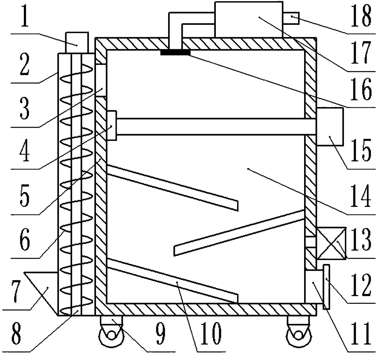
A straw pulverizing and drying device technology, which is applied in the directions of drying gas arrangement, drying, drying machine, etc., can solve the problems of lack of simple structure, convenient use and low price, the pulverization effect cannot meet the processing requirements, and the pulverization and drying process is dispersed, etc. To achieve the effect of easy promotion, high pulverization and drying efficiency, and increased residence time

Inactive Publication Date: 2018-06-19
ZHENGZHOU HAOEN ELECTRONICS INFORMATION TECH CO LTD
View PDF7 Cites 3 Cited by
  • Summary
  • Abstract
  • Description
  • Claims
  • Application Information

AI Technical Summary

Problems solved by technology

[0002] With the development of animal husbandry, implementing the combination of agriculture and animal husbandry, raising animals with straw, and forming a grain-saving animal husbandry structure is an effective way for the development of animal husbandry in line with my country's national conditions; my country's rural areas are rich in straw resources, and straw burning causes a lot of pollution. Straw cutting and processing machinery is also widely used; these machines can expand the source of feed, improve the quality of straw, and avoid waste of roughage stems from being eaten; but the crushing effect of existing straw crushing machinery cannot meet the processing needs, and the crushing is not thorough The pulverization and drying process is scattered, the efficiency is low, and there is a lack of models with simple structure, convenient use, low price, and suitable for the majority of individual farmers.

Method used


Image

  • Portable straw smashing and drying device
  • Portable straw smashing and drying device
  • Portable straw smashing and drying device

Examples


Embodiment Construction

[0016] The technical solution of the present patent will be described in further detail below in conjunction with specific embodiments.

[0017] Embodiments of the present patent are described in detail below, examples of which are illustrated in the accompanying drawings, wherein the same or similar reference numerals refer to the same or similar elements or elements having the same or similar functions throughout. The embodiments described below with reference to the accompanying drawings are exemplary and are only used to explain the present patent, but should not be construed as a limitation on the present patent.

[0018] In the description of this patent, it should be understood that the terms "center", "upper", "lower", "front", "rear", "left", "right", "vertical", "horizontal", The orientation or positional relationship indicated by "top", "bottom", "inner", "outer", etc. is based on the orientation or positional relationship shown in the drawings, and is only for the ...


PUM


Abstract

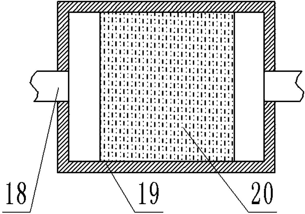
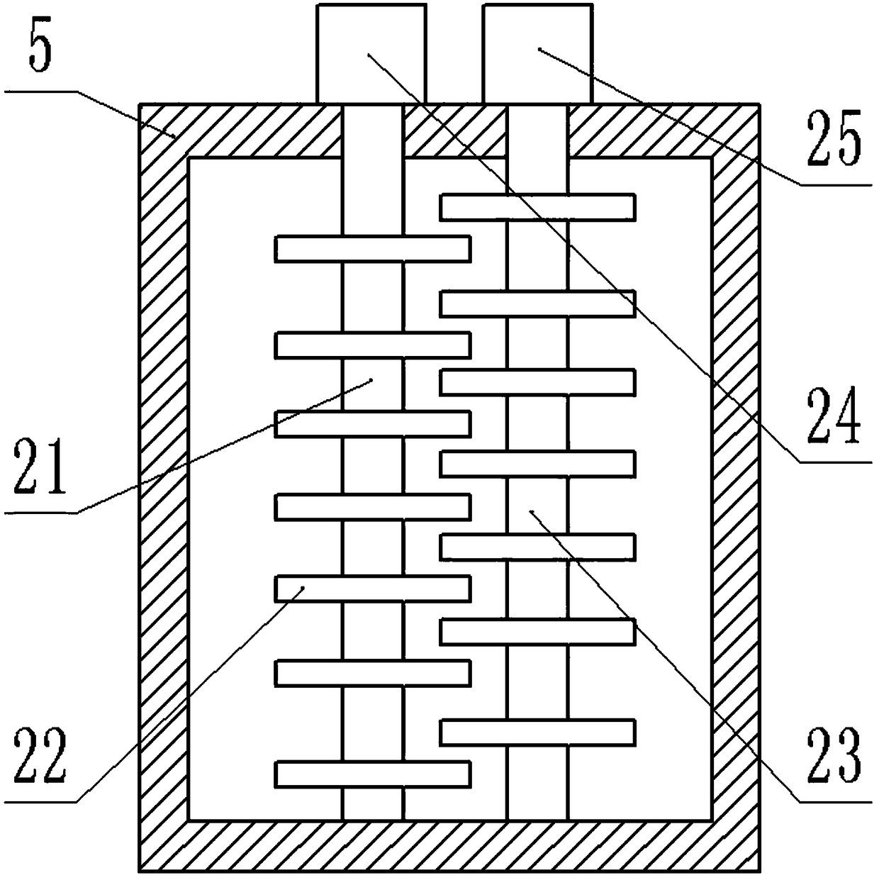
The invention provides a portable straw smashing and drying device and belongs to the field of smashing and drying devices. The device includes a shell body, an oblique baffle, a smashing device and afiltering device; the shell body is cubic and is vertically placed, and a smashing cavity is formed in the shell body; the left end of the smashing cavity is provided with a connection port connectedto the shell body; a material conveying device is arranged at the left end of the connection port; the material conveying device includes a rotating motor, a material conveying shell, material conveying vanes, a feeding port and a rotating main shaft; the rotating motor is arranged at the upper end and fixedly connected to the upper surface of the material conveying shell, and the connected rotating main shaft is arranged at the lower end of the rotating motor; the lower end of the rotating main shaft is connected to the inner surface of the material conveying shell, and the fixedly connectedmaterial conveying vanes are arranged on the rotating main shaft; the material conveying shell is spiral; a connected exhaust pipe is arranged at the upper end of the smashing cavity; the smashing device connected to the shell body is arranged at the lower end of a filtering net. The device is simple in structural design, convenient to use, high in smashing and drying efficiency, low in price andconvenient to popularize.

Description

technical field [0001] The invention relates to a pulverizing and drying device, in particular to a convenient straw pulverizing and drying device. Background technique [0002] With the development of animal husbandry, implementing the combination of agriculture and animal husbandry, raising livestock with straw, and forming a grain-saving animal husbandry structure is an effective way to develop animal husbandry in line with my country's national conditions; my country's rural areas are rich in straw resources, and straw burning causes a lot of pollution. Straw cutting and processing machinery has also been widely used; these machines can expand the source of feed, improve the quality of straw, and avoid the waste of roughage stalks without being eaten; however, the existing straw pulverization machinery can not meet the processing requirements, and the pulverization is not complete. The pulverization and drying process is scattered, low in efficiency, and lacks a model with...

Claims


Application Information

Patent Timeline
Patent Type & Authority Applications(China)
IPC IPC(8): A01F29/02B01D53/04F26B21/00
CPCA01F29/02B01D53/04F26B21/004
Inventor 刘继军
Owner ZHENGZHOU HAOEN ELECTRONICS INFORMATION TECH CO LTD
Learn More