
Port connection for a heat exchanger

A technology for plate heat exchangers and connectors, which is used in heat exchanger fixing, heat exchange equipment, heat exchanger shells, etc., can solve the problems of high labor intensity and time-consuming, and achieve the effect of reducing cost and time.

Active Publication Date: 2018-06-08
SPX SHANGHAI FLUID TECH
View PDF11 Cites 2 Cited by
  • Summary
  • Abstract
  • Description
  • Claims
  • Application Information

AI Technical Summary

Problems solved by technology

These methods are labor intensive, time consuming and / or require specific tooling for each port size

Method used


Image

  • Port connection for a heat exchanger
  • Port connection for a heat exchanger
  • Port connection for a heat exchanger

Examples


Embodiment Construction

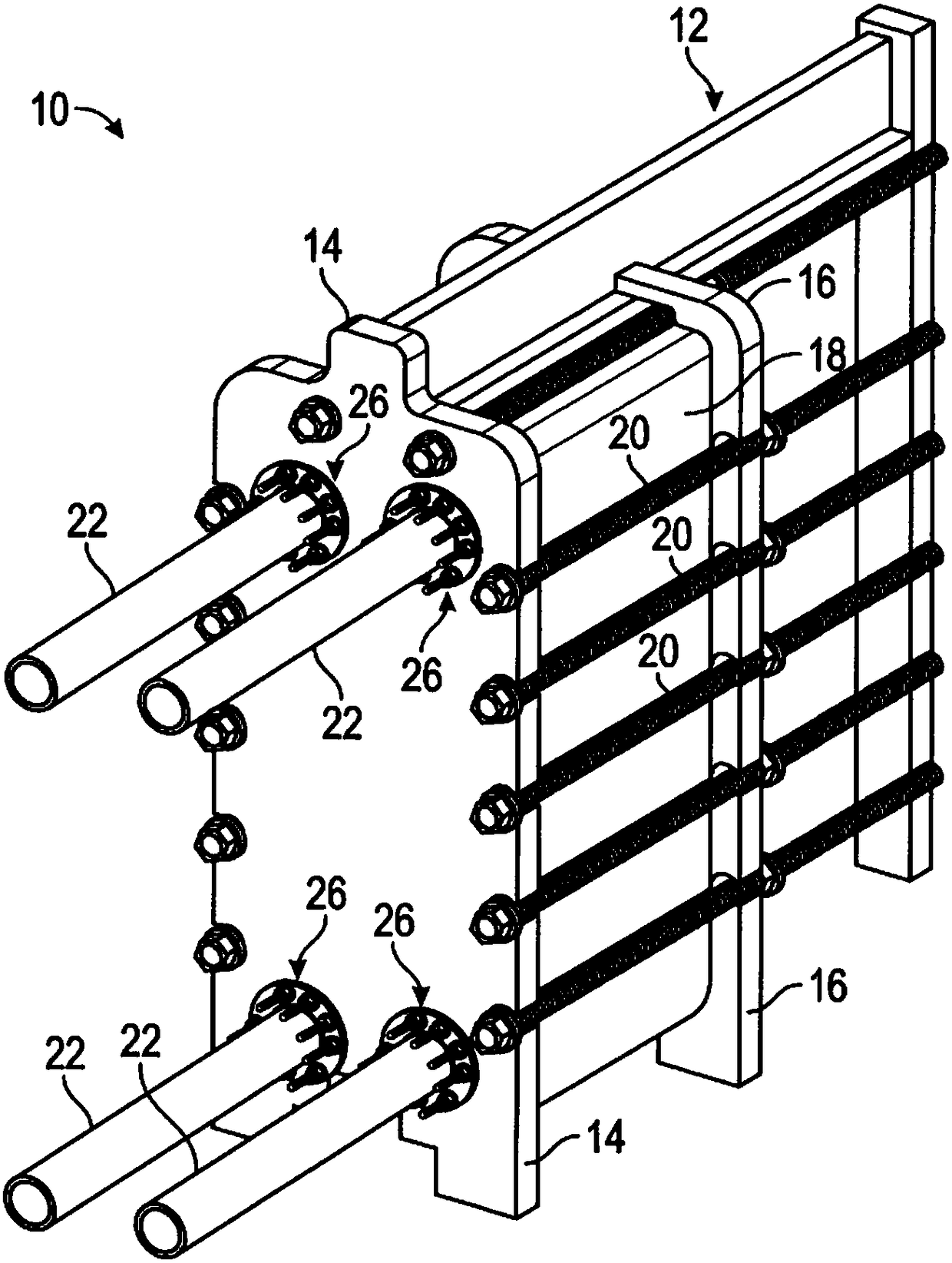
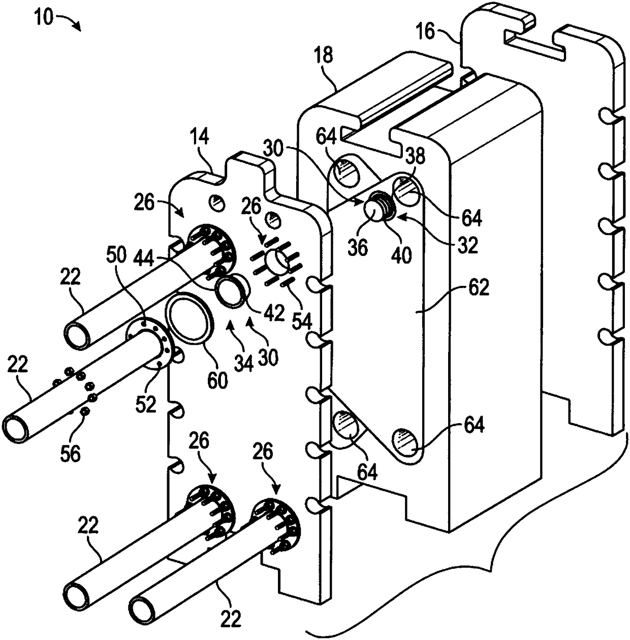
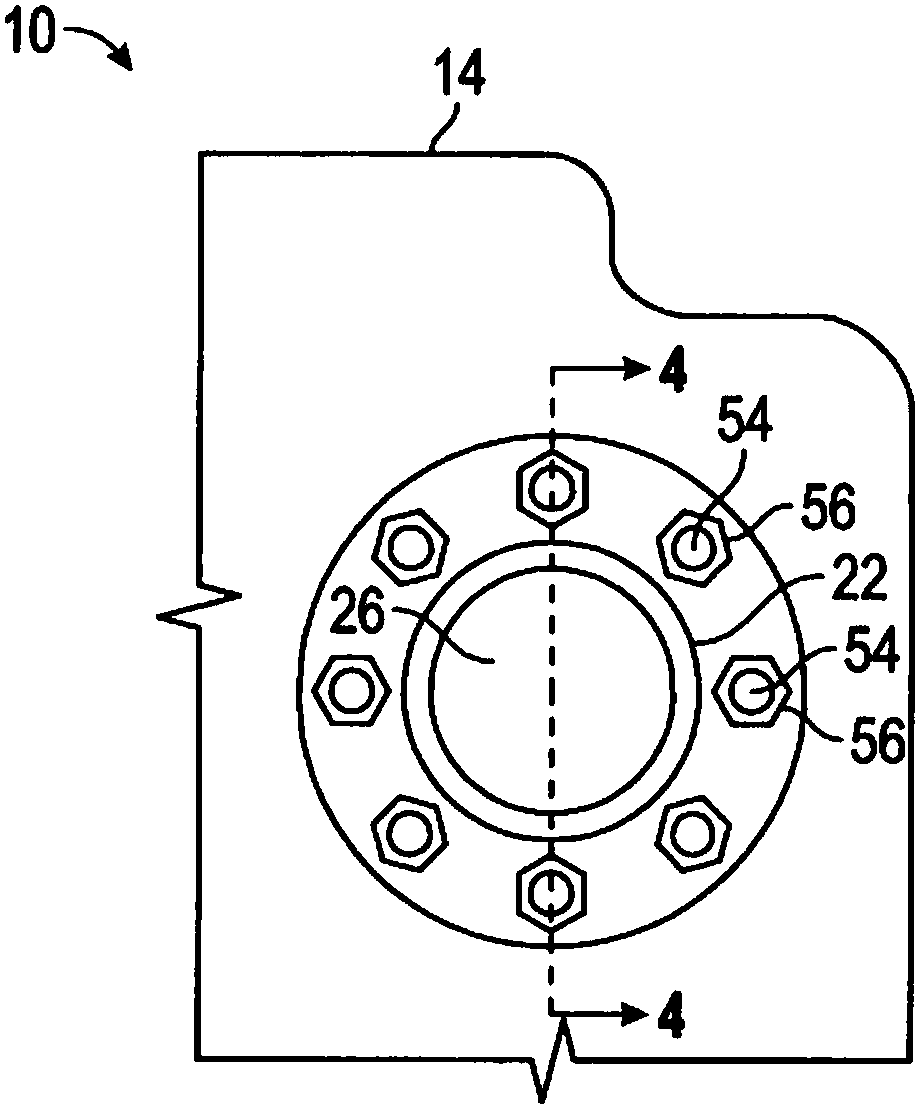
[0019] In general, embodiments of the present invention relate to port connections for heat exchangers and methods of assembling improved port connections in ports of pressure plates of heat exchangers that are more robust than conventional port connections. Ease of installation and / or maintenance, and / or cost savings compared to traditional port connections. In addition to the ease of installation, improved maintenance, and reduced cost of the improved port connections described herein, tooling and machine costs are reduced by omitting welding and / or hydroforming associated with conventional port connection installations.

[0020] Referring now to the drawings, in which like reference numerals denote like elements, figure 1 is a perspective view of a heat exchanger 10 suitable for use with embodiments of the invention. Such as figure 1 As shown, heat exchanger 10 includes a frame 12 having a pair of pressure plates 14 and 16 , a plate pack 18 , a plurality of tie rod assemb...


PUM


Abstract

A port connection includes a first element, a second element, and a seal. The first element has a first sleeve and a first flange. The first sleeve is configured to slide into a port disposed througha pressure plate of the plate heat exchanger and the first flange having a first bearing surface to bear upon a first face of the pressure plate. The second element has a second sleeve and a second flange. The second sleeve is configured to slide into the port and the second flange having a second bearing surface to bear upon a second face of the pressure plate. The seal is generated in response to the first sleeve telescoping into the second sleeve.

Description

technical field [0001] The present invention generally relates to plate heat exchangers. More specifically, the present invention relates to port connections for plate heat exchangers. Background technique [0002] Plate heat exchangers provide efficient heat transfer from one fluid to another in a relatively small volume. Heat exchangers are usually assembled from a number of individual or welded pairs of plates, called a plate pack, which are sealed around the outer edges with gasket material. The plate pack is compressed within the frame of the heat exchanger to form a seal between the plates or pairs of plates. The plate pack includes inlets and outlets for both fluids. [0003] Apply compressive force evenly to the surface of the plate pack to prevent leakage from the seals and reduce damage to the plates. Due to the size of the plate pack and the amount of pressure applied, the plate pack is inserted between two pressure plates called a head and follower, which ser...

Claims


Application Information

Patent Timeline
Patent Type & Authority Applications(China)
IPC IPC(8): F28F3/08F28F3/10F28F5/00F28F9/04F28F9/12F16L41/00F16L41/12F16L41/14
CPCF16L41/00F16L41/12F16L41/14F28F3/08F28F3/10F28F5/00F28F9/04F28F9/12F16L41/086F28F2275/20F28F2280/06F28F2275/205F28F3/083F28F9/0246F28F9/0256F28D9/005F28F9/0248
Inventor 耶斯·汉森·彼得森
Owner SPX SHANGHAI FLUID TECH
Learn More