
Submarine natural gas pipeline leakage monitoring experimental platform and data processing method thereof

A natural gas pipeline and experimental platform technology, which is applied in the field of submarine natural gas pipeline leakage monitoring experimental platform, can solve the problems of calculating the change of optical fiber phase, insensitivity to judgment of leakage, and weak light intensity of photoelectric detectors, etc. Necessary interference, improved positioning accuracy, and simple construction effects

Pending Publication Date: 2018-06-08
ZHEJIANG UNIV OF TECH
View PDF8 Cites 1 Cited by
  • Summary
  • Abstract
  • Description
  • Claims
  • Application Information

AI Technical Summary

Problems solved by technology

[0003] The existing pipeline leakage monitoring technology based on the principle of optical fiber sensing has the following problems: 1. The optical path is complicated and too many optical devices are used, resulting in a large loss of optical power
As a result, the intensity of light received by the photodetector is weak, and it is not sensitive to the judgment of leakage
2. The current optical fiber sensing demodulation principle uses a large number of integral and differential mathematical operations, and there are too many parameters that need to participate in the operation, which brings inevitable new error sources
It is difficult to quickly and accurately calculate the phase change in the fiber, which brings a huge positioning error

Method used


Image

  • Submarine natural gas pipeline leakage monitoring experimental platform and data processing method thereof
  • Submarine natural gas pipeline leakage monitoring experimental platform and data processing method thereof

Examples


Embodiment Construction

[0025] The invention will be further described below in conjunction with the accompanying drawings of the description.

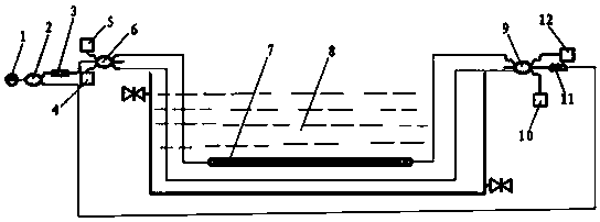
[0026] like Figure 1-2 As shown, an experimental platform based on natural gas pipeline leakage monitoring and its data processing method includes a laser source 1, a third optical coupler 2, a first polarization controller 3, a second photodetector 4, and a first photodetector 5 , the first optical coupler 6, the rigid polyvinyl chloride pipe 7 of the prefabricated leakage hole, the stainless steel tank without a cover 8, the second optical coupler 9, the third photodetector 10, the second polarization controller 11 and the fourth photodetector Device 12.

[0027] The experimental platform includes an optical path system, a photoelectric detection signal processing system and a scene simulation system; the optical path system includes: a laser source 1, a third optical coupler 2, a first polarization controller 3, a second photodetector 4, a first photode...


PUM


Abstract

The invention discloses a submarine natural gas pipeline leakage monitoring experimental platform and a data processing method thereof. The submarine natural gas pipeline leakage monitoring experimental platform comprises an optical path system, a photoelectric detection system, a signal processing system and a scene simulation system. The optical path system is provided with a first optical fiberset and a second optical fiber set in a connected mode. The first optical fiber set enters the scene simulation system in the clockwise direction and penetrates out of the scene simulation system, and the second optical fiber set enters the scene simulation system in the counterclockwise direction and penetrates out of the scene simulation system. The first optical fiber set and the second optical fiber set penetrate out of the scene simulation system and then are connected with the photoelectric detection system, and the photoelectric detection system is in circuit connection with the signalprocessing system. The submarine natural gas pipeline leakage monitoring experimental platform and the data processing method thereof have the beneficial effects that by adopting the experimental platform, the application number of optical instruments is greatly decreased, the loss of optical power on an optical path and unnecessary interference are greatly reduced, setting-up of the optical pathof the experimental platform is easy, and meanwhile, the experimental cost is reduced.

Description

technical field [0001] The invention relates to the technical field of gas transmission pipeline safety monitoring, in particular to an experimental platform for monitoring leakage of a submarine natural gas pipeline and a data processing method thereof. Background technique [0002] Pipeline transportation has the advantages of low cost, high efficiency, low loss, good stability, and adaptability to complex terrain and climate. For submarine natural gas pipelines, the transmitted natural gas has a high content of acidic sulfides, which is prone to natural gas leakage caused by pipeline corrosion. If pipeline leakage is not found in time and repaired in time, it will bring huge economic losses. It is also a great waste of natural resources. The sulfide leaked into the ocean will seriously threaten the ecological environment of the nearby sea area. Therefore, the monitoring and safety maintenance of the operating status of submarine natural gas pipelines are becoming more ...

Claims


Application Information

Patent Timeline
Patent Type & Authority Applications(China)
IPC IPC(8): F17D5/06F17D5/00G06F17/50
CPCF17D5/005F17D5/06G06F2113/14G06F30/20
Inventor 罗利佳谢礼阳包士毅许漫
Owner ZHEJIANG UNIV OF TECH
Learn More