Auxiliary drive device of variable-pitch system and control method thereof

An auxiliary drive and pitch system technology, which is applied in the control of wind turbines, wind turbines and motors that store electricity, etc., can solve the problems of short maintenance cycle, destruction of wind turbine towers, poor low temperature resistance, etc., to improve safety. , The effect of reducing installation equipment and simplifying the installation process

Active Publication Date: 2018-06-08
CHONGQING HUAYU HEAVY IND ELECTROMECHANICAL CO LTD
View PDF4 Cites 3 Cited by
  • Summary
  • Abstract
  • Description
  • Claims
  • Application Information

AI Technical Summary

Problems solved by technology

However, the battery's short service life, short maintenance cycle and poor low temperature resistance have become fatal flaws hindering its development.
The second type of product uses supercapacitors as a backup power supply, which better solves the problems of service life and low-temperature performance, but the operation control of this product, the execution of system fault processing results, manual and automatic, all rely entirely on the servo drive, and once If the servo drive itself fails, the blades will not be able to return to the zero power angle position, thus making the entire wind turbine in an unsafe state
There have been many devastating incidents in wind farms where the blades could not return to a safe position due to backup power failure
In addition, when these two products are installed on the blades in the wind farm, an additional set of electric auxiliary power supply for charging the battery or super capacitor or power supply equipment for directly driving the actuator motor is required, which increases the cumbersomeness of the blade installation process.

Method used


Image

  • Auxiliary drive device of variable-pitch system and control method thereof
  • Auxiliary drive device of variable-pitch system and control method thereof
  • Auxiliary drive device of variable-pitch system and control method thereof

Examples


Embodiment Construction

[0033] The present invention will be further described in detail below in conjunction with the accompanying drawings.

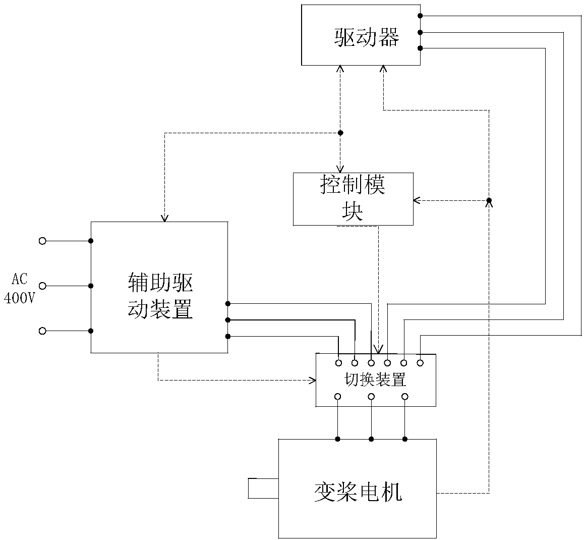
[0034] like figure 1 As shown, the present invention discloses an auxiliary drive system of a pitch system, including a pitch motor, a driver and a control module, the driver is connected to the control module, and also includes an auxiliary drive device and a switching device, wherein:

[0035] The output end of the auxiliary driving device is connected in parallel with the output end of the driver through the input end of the switching device, the output end of the switching device is connected with the pitch motor, and the auxiliary driving device and the switching device are respectively connected in communication with the control module;

[0036] When the control module detects that the drive is working normally, the control module sends speed and direction commands to the drive, and the drive drives the pitch motor to run according to the speed, directi...


PUM


Abstract

The invention discloses an auxiliary drive system of a variable-pitch system. A driver is connected with a control module, the output end of an auxiliary drive device and the output end of the driverare connected in parallel through the input end of a switching device, the output end of the switching device is connected with a variable-pitch motor, and the auxiliary drive device and the switchingdevice are in communication with the control module. When the driver fails, the power supply of the variable-pitch motor is switched to the output end of the auxiliary drive device, it is ensured that the variable-pitch system still can make blades return to a zero power angle when the driver fails, the defect that drive control over a variable-pitch motor by a variable-pitch system completely depends on a driver is overcome, and the safety of the variable-pitch system and even the whole unit can be improved. Meanwhile, by using the auxiliary drive device for phase control, steering control over the variable-pitch motor can be achieved, so that no additional auxiliary power supply is needed during blade installation and calibration in a wind power plant, installation equipment is reduced,and the installation process is simplified.

Description

technical field [0001] The invention relates to the technical field of wind power generation, in particular to an auxiliary drive device of a pitch system and a control method thereof. Background technique [0002] Wind energy is a new type of renewable and environmentally friendly energy, and wind power generation projects are key projects actively supported by the national industrial policy. In recent years, wind power has developed rapidly in my country. Wind turbines have experienced the rapid development of fixed pitch stall type, full blade variable pitch type, variable speed type based on variable speed and constant frequency technology, and intelligent type. During this development process, the development of wind turbine control technology has played a decisive role. , and the development of blade control technology has played an important role in promoting the development of the overall technology. The pitch control system is an important part of modern large win...

Claims


Application Information

Patent Timeline
Patent Type & Authority Applications(China)
IPC IPC(8): F03D7/04F03D9/11F03D80/00
CPCF03D7/022F03D7/047F03D9/11F03D80/00Y02E10/72Y02E70/30
Inventor 赵胜武胡小华唐胜谢敬朗黄学静
Owner CHONGQING HUAYU HEAVY IND ELECTROMECHANICAL CO LTD
Why Eureka
Try Eureka