
A hovering flapping-wing aircraft and its flight control method

A flapping-wing aircraft and aircraft technology, applied in the field of aircraft, can solve problems such as increasing control complexity, increasing weight, and asymmetry of flapping wing motion, and achieve the effects of reducing control complexity, reducing weight, and improving operating efficiency

Active Publication Date: 2016-04-27
SUZHOU TAOXUN AVIATION TECH CO LTD
View PDF4 Cites 1 Cited by
  • Summary
  • Abstract
  • Description
  • Claims
  • Application Information

AI Technical Summary

Problems solved by technology

[0003] In the prior art, the common flapping wing aircraft has the following problems: (1) the flapping wing movement is asymmetrical
Most of the flapping wing aircraft use the steering gear to drive the additional wing surface to realize the steering of the fuselage. This design increases the weight on the one hand, and increases the control complexity on the other hand.

Method used


Image

  • A hovering flapping-wing aircraft and its flight control method
  • A hovering flapping-wing aircraft and its flight control method
  • A hovering flapping-wing aircraft and its flight control method

Examples


Embodiment 1

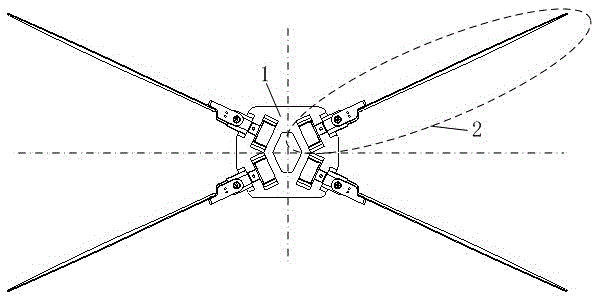
[0023] A hovering or flapping-wing aircraft disclosed in the scheme of the present invention, as attached figure 1 And attached figure 2 Shown, comprise fuselage 1 and four sets of single flapping wing mechanism 2. Four sets of single flapping wing mechanisms 2 are symmetrically arranged on both sides of the fuselage 1 symmetrically. Through this symmetrical configuration, the flapping-wing aircraft can realize stable hovering.

[0024] as attached image 3 As shown, the single flapping wing mechanism 2 includes a swing bracket 5 and a flapping wing 7 . Wherein, the swing bracket 5 is connected to the fuselage 1 through a hinge, and the included angle θ between the hinge axis and the vertical direction of the plane where the fuselage 1 is located is a small acute angle, and the range of the acute angle is 3° to 20° (including 3° and 20°). Flapping wing 7 is fixedly connected with swing support 5. In this way, the flapping wing 7 can flutter laterally at a small inclinat...


PUM


Abstract

The invention discloses a flapping-wing air vehicle capable of hovering as well as a flight control method thereof. The flapping-wing air vehicle capable of hovering comprises a vehicle body and four single-flapping-wing mechanisms, wherein the four single-flapping-wing mechanisms are mounted on two sides of the vehicle body in a left-and right and front-and-back symmetrical manner, each single-flapping-wing mechanism comprises a swinging support, a flapping wing, an actuator, an eccentric bent rod and limit rods, the swinging supports are connected with the vehicle body through hinges, the included angle formed by each hinge shaft and the vertical direction of the plane where the vehicle body is located is a small acute angle, the flapping wings are fixedly connected with the swinging supports, the actuators are fixedly mounted on the vehicle body, every two limit rods are fixedly mounted on each swinging support, one end of each eccentric bent rod is fixedly connected with an output end of each actuator, the other end of each eccentric bent rod is bent, each bent section is inserted between every two limit rods, and rotation of output shafts of the actuators is converted into swinging of the swinging supports by the aid of eccentric rotation. The air vehicle is small in size, light in weight and capable of hovering stably during flight, the flapping wings can produce the larger lifting force and provide the enough lateral force, various maneuvering actions can be realized conveniently, flapping-wing swinging mechanisms are simple and reliable, and the actuating efficiency is high.

Description

technical field [0001] The invention relates to the field of aircraft, in particular to a hovering flapping-wing aircraft and its flight control method. Background technique [0002] In nature, the flapping wing flight of birds or insects can achieve rapid take-off, acceleration and hovering, with high maneuverability and flexibility. Because of its small size and light weight, the flapping wing aircraft has more advantages in small spaces and has good concealment, so it has very broad application prospects in military and civilian applications. Experts from various countries have successively developed a series of bionic flapping-wing aircraft such as "iBird-bot", "MicroroboticFly", "Hummingbird", "DelflyMicro" and "SmartBird", which have made technical breakthroughs in flying forward, backward and hovering. [0003] In the prior art, the common flapping wing aircraft has the following problems: (1) The flapping wing movement is asymmetrical. Many flapping-wing aircraft u...

Claims


Application Information

Patent Timeline
Patent Type & Authority Patents(China)
IPC IPC(8): B64C33/02
Inventor 葛讯段文博沈元
Owner SUZHOU TAOXUN AVIATION TECH CO LTD
Learn More