a cleaning device

A technology for cleaning devices and cover plates, applied in the field of cleaning, can solve the problems of not being able to brush a barrel or device, not being able to ensure the cleanliness of the inner wall of a holding cavity, and not being able to add chemical cleaning agents, etc., so as to achieve the effect of ensuring the cleanliness.

Active Publication Date: 2019-10-18
徐州天骋智能科技有限公司
View PDF4 Cites 0 Cited by
  • Summary
  • Abstract
  • Description
  • Claims
  • Application Information

AI Technical Summary

Problems solved by technology

[0003] The existing technology has the following technical problems: 1. The existing technology cannot scrub the inner wall of the storage cavity of the barrel or device, and cannot ensure the cleanliness of the inner wall of the storage cavity; When cleaning the inner wall of the storage cavity, it is not possible to intermittently add chemical cleaning agents to the storage cavity, and the cleanliness of the inner wall of the storage cavity cannot be guaranteed

Method used


Image

  • a cleaning device
  • a cleaning device
  • a cleaning device

Examples


Embodiment Construction

[0021] The present invention will be described in further detail below by means of specific embodiments:

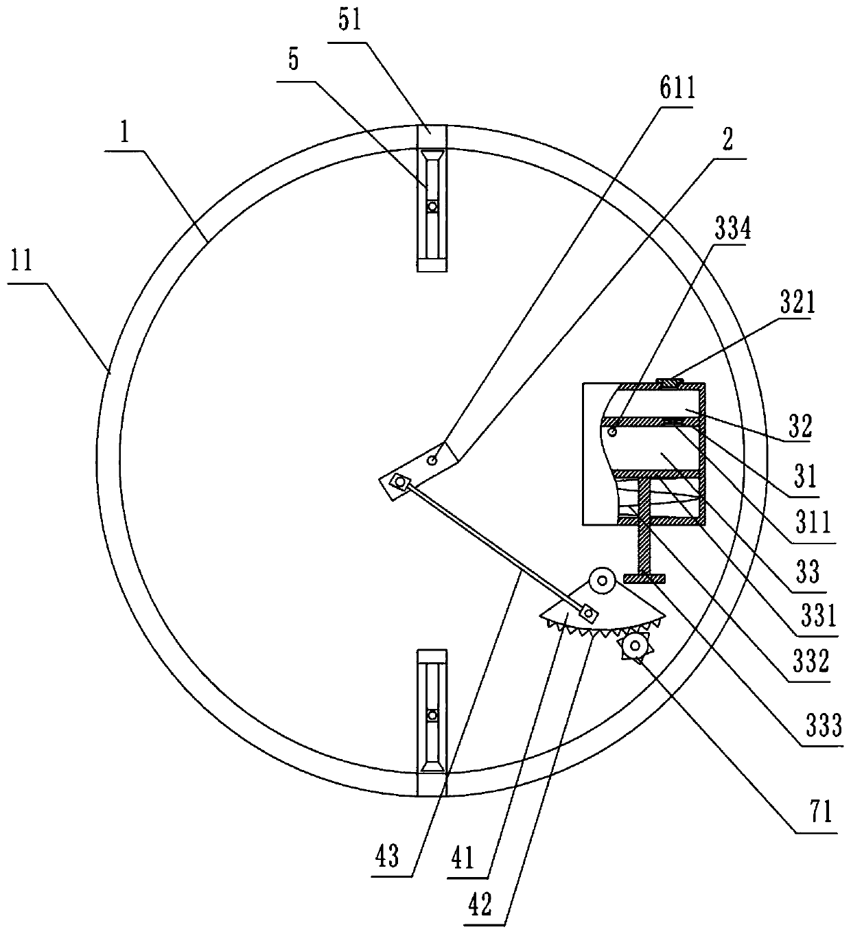
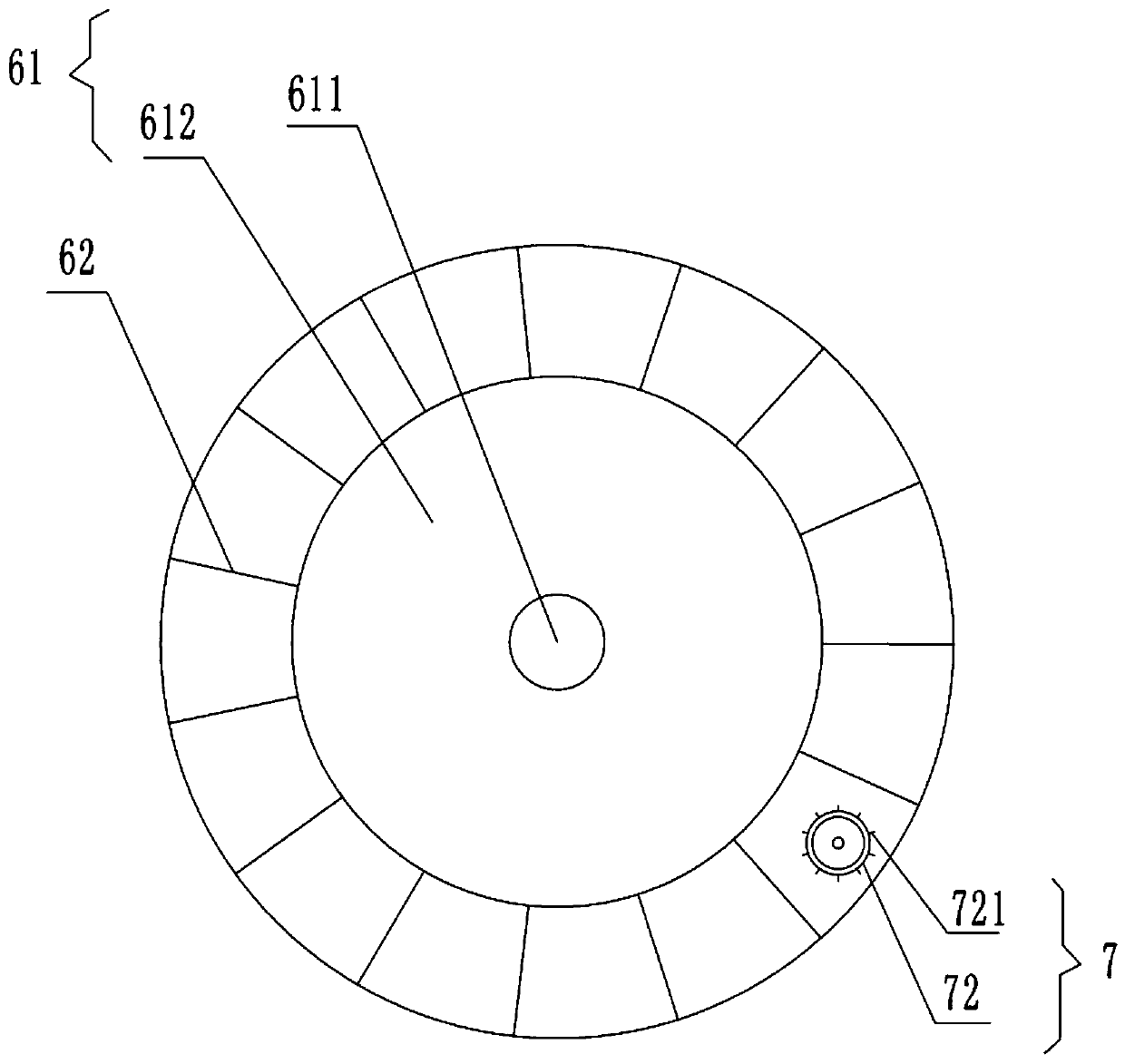
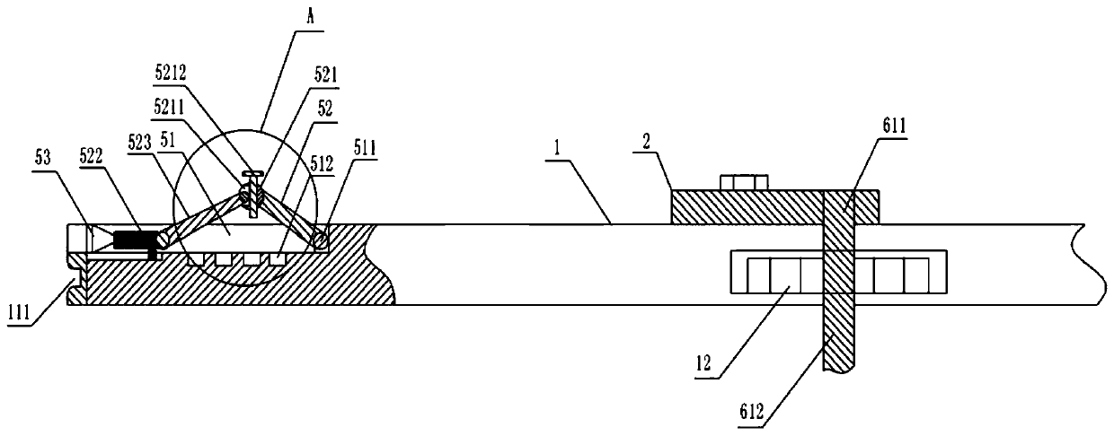
[0022] The reference signs in the drawings of the description include: cover plate 1, rubber layer 11, biaxial motor 12, rotating block 2, partition plate 31, connecting pipe 311, feed chamber 32, cover 321, discharge chamber 33, piston 331, return spring 332, piston rod 333, discharge pipe 334, sector plate 41, rack 42, connecting rod 43, positioning part 5, positioning groove 51, rotating shaft 511, positioning hole 512, fixed rod 52, positioning shaft 521 , strip groove 5211, screw 5212, sliding rod 522, extension rod 523, suction cup 53, rotating shaft 61, upper shaft 611, lower shaft 612, brush bar 62, cleaning shaft 7, gear 71, cleaning roller 72, sheet-like protrusion 721.

[0023] In order to achieve the above object, the basic scheme of the present invention is as follows:

[0024] Such as figure 1 and as figure 2 As shown, a cleaning device includes a cover...


PUM


Abstract

The invention relates to the technical field of cleaning, in particular to a cleaning device. The device comprises a cover plate for cooperating with a barrel or a device holding cavity, wherein a rubber layer is arranged at the edge of the cover plate; a cavity is formed in the cover plate, and a motor is arranged in the cavity; the surface of the cover plate is provided with a rotating block, afeeding part, a pressing part, a positioning part and a rotating part driven by the motor; a cleaning shaft is also rotatably connected to the cover plate, gears meshed with a rack are fixed to one end of the cleaning shaft, and the other end of the cleaning shaft is provided with a cleaning roller for extending into the barrel and the device holding cavity and cleaning the rotating part. The device can scrub the inner wall of the cavity and intermittently add chemical engineering product cleaning agent to ensure the cleanliness of the inner wall of the cavity.

Description

technical field [0001] The invention relates to the technical field of cleaning, in particular to a cleaning device. Background technique [0002] In the process of chemical production, due to various reasons, dirt such as polymers, coking, oil dirt, scale, sediments, corrosion products, etc. will occur in equipment and pipelines. These have seriously affected the use of equipment, so it is very important to clean chemical equipment. Especially for the cleaning of barrels or devices containing chemicals, since the holding chamber of the barrel or device holds chemicals for a long time, there will be a lot of dirt on the inner wall of the holding chamber of the barrel or device. For the inner wall of the cavity, the prior art discloses a Chinese utility model patent with the notification number CN205797945U, a device for cleaning chemical barrels, which includes an upper barrel part for arranging the chemical barrels and placing the chemical barrels to the cleaning position....

Claims


Application Information

Patent Timeline
Patent Type & Authority Patents(China)
IPC IPC(8): B08B9/087B08B9/08B08B13/00
Inventor 夏林逢
Owner 徐州天骋智能科技有限公司
Why Eureka
Try Eureka