Polarity reversal output-type inverter with power decoupling and control method thereof
A technology of polarity reversal and power decoupling, applied in output power conversion devices, conversion of AC power input to DC power output, electrical components, etc. It can solve the problems of large size, low reliability, and unstable filtering performance.
- Summary
- Abstract
- Description
- Claims
- Application Information
AI Technical Summary
Problems solved by technology
Method used
Image
Examples
Embodiment Construction
[0027] Below in conjunction with accompanying drawing, the technical scheme of invention is described in detail:
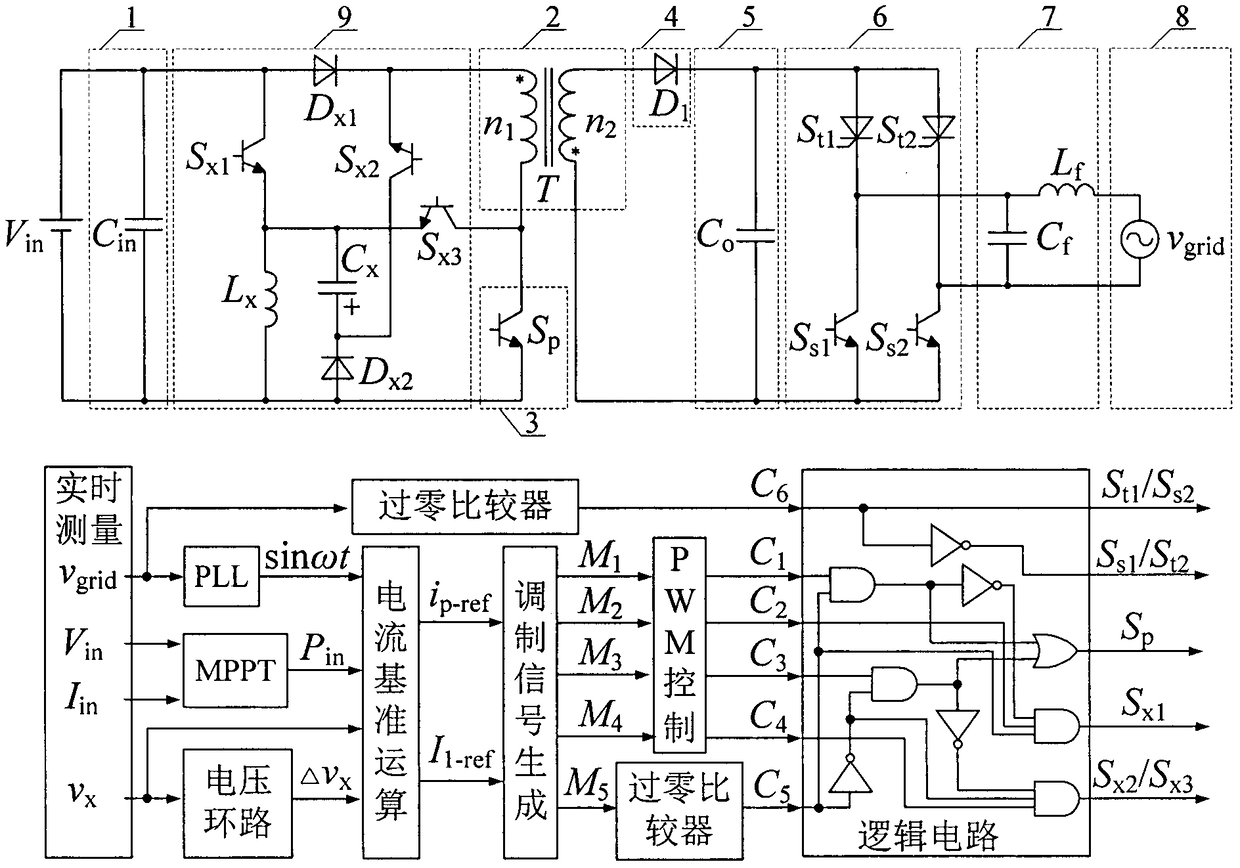
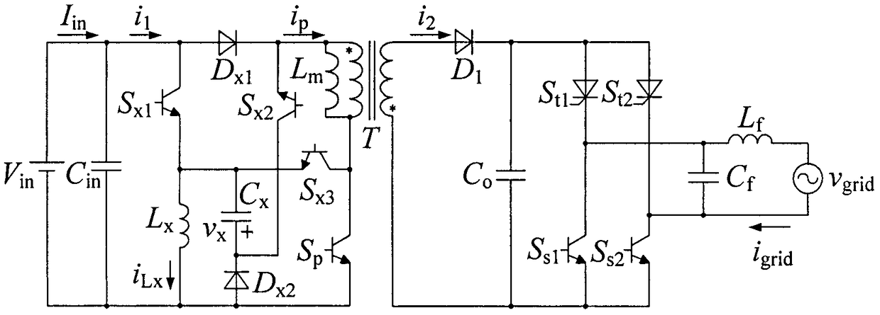
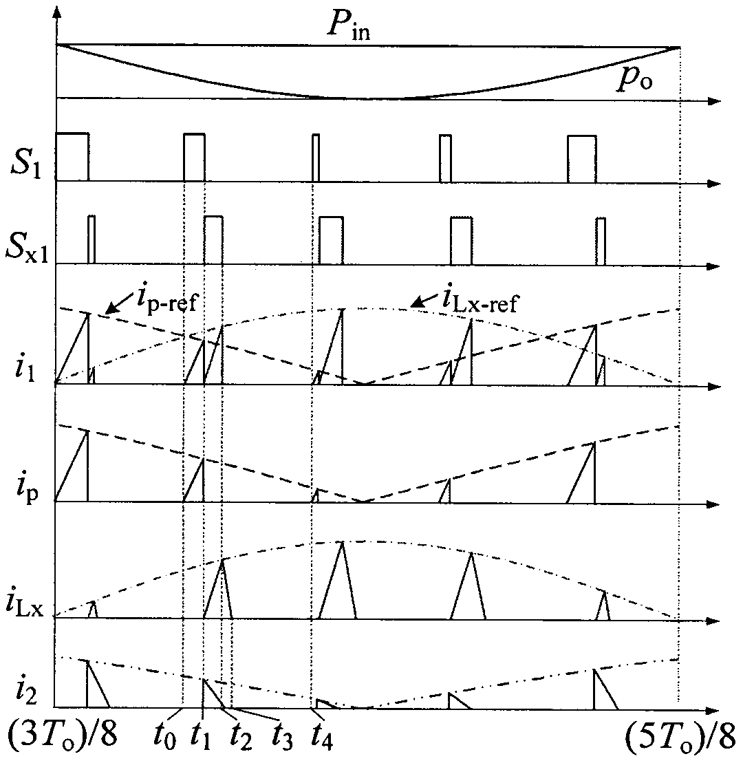
[0028] attached figure 1 What is shown is a structural schematic diagram of a main circuit of a polarity inversion output type inverter with power decoupling and its control method. The main circuit of the polarity inversion output inverter with power decoupling consists of a DC power supply, an input capacitor 1, an isolation transformer 2, a primary switch tube 3, a cut-off diode 4, a filter capacitor 5, and a polarity inversion inverter bridge 6 , filter circuit 7, grid 8 and decoupling circuit 9. C in is the input capacitance, S p is the primary switch tube, S x1 ~S x3 is the decoupling switch tube, L x is the decoupling inductance, D x1 、D x2 is the decoupling diode, C x is the decoupling capacitor, T is the isolation transformer, D 1 is the cut-off diode, C o is the filter capacitor, S t1 , S t2 is the thyristor, S s1 , S s2 is the switching t...
PUM
 Abstract
Description
Claims
Application Information
 - R&D Engineer
- R&D Manager
- IP Professional
- Industry Leading Data Capabilities
- Powerful AI technology
- Patent DNA Extraction
Browse by: Latest US Patents, China's latest patents, Technical Efficacy Thesaurus, Application Domain, Technology Topic, Popular Technical Reports.
© 2024 PatSnap. All rights reserved.Legal|Privacy policy|Modern Slavery Act Transparency Statement|Sitemap|About US| Contact US: help@patsnap.com


