Processing chip treatment system for numerical controlled milling machine for brittle metal material cutting process

A brittle metal, CNC milling machine technology, applied in metal processing equipment, metal processing machinery parts, milling machines, etc., can solve the problems of restricting the work efficiency of operators, increasing the difficulty of cleaning, and increasing the workload of cleaning, so as to reduce loss, The effect of reducing the amount of cleaning and reducing noise

Active Publication Date: 2018-06-05
开平正霖卫浴实业有限公司
View PDF8 Cites 7 Cited by
  • Summary
  • Abstract
  • Description
  • Claims
  • Application Information

AI Technical Summary

Problems solved by technology

[0003] A large amount of cutting chips will be generated during the milling process. The chip removal device of the existing turret milling machine only has a chip collection box at the bottom. In the actual processing process, the chips are cleaned by manual sweeping, and some chips will enter the workbench In the groove, it increases the difficulty of cleaning, and even scratches the operator's palm; and it also needs to clean the chip box twice; this seriously restricts the operator's work efficiency; The following problems will exist in the broken chips: the chips fly randomly, which is easy to burn the operator, and even fly into the operator's eyes, causing serious consequences; the chips splash in a large range, which increases the cleaning workload and affects the work efficiency

Method used


Image

  • Processing chip treatment system for numerical controlled milling machine for brittle metal material cutting process
  • Processing chip treatment system for numerical controlled milling machine for brittle metal material cutting process
  • Processing chip treatment system for numerical controlled milling machine for brittle metal material cutting process

Examples


Embodiment approach

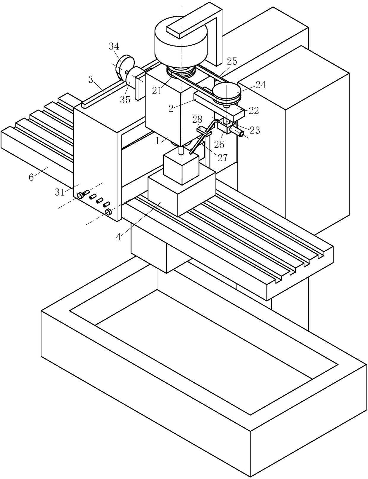
[0030] As an embodiment of the present invention, the injection module 2 includes a socket pulley 21, a mounting frame 22, a rotating shaft 23, a connecting pulley 24, a belt 25, an impeller box 26, a pipeline 27 and a support frame 28; The belt pulley 21 is fixedly installed on the milling machine spindle through bolts; the mounting frame 22 is fixedly mounted on one side of the milling machine headstock 1 through bolts; the rotating shaft 23 is mounted on the mounting frame 22 through bearing rotation; the upper end of the rotating shaft 23 is fixedly connected to The connecting pulley 24; the connecting pulley 24 and the sleeve pulley 21 are sheathed with a belt 25; the rotation of the main shaft can drive the connecting pulley 24 to rotate; the lower end of the rotating shaft 23 is fixedly connected to the impeller; the impeller is installed in the impeller box 26 for rotation; The impeller box 26 is fixedly installed on the lower end of the mounting frame 22; one side of t...


PUM


Abstract

The invention belongs to the technical field of machine processing equipment, and particularly relates to a processing chip treatment system for a numerical controlled milling machine for a brittle metal material cutting process. The system comprises a jet module, a chip stop module and a chip discharge pipe, wherein the jet module is arranged on one side of a main shaft tank of a milling machine,comprises a sleeve joint belt pulley, a mount rack, a rotating shaft, a connection belt pulley, a belt, an impeller casing, a pipeline and a support frame, and is used for blowing chips of a millingmachine to the chip stop module; the chip stop module comprises a tank body, a chip stop plate, a spring, a cam, a vibration motor and a guide plate, is arranged on one side of a chip-cutting platformof the milling machine, and is used for retaining chips blown by the jet module; and the chip discharge pipe is arranged at the lower end of one side of the chip stop module. The processing chip treatment system is especially suitable for cleaning broken chips of a brittle material, can generate high-pressure air flow through rotation of a main shaft; chips are intensively blown to the chip stopplate, are concentrated, and can avoid chip splashing, so that the cleaning workload of an operator can be reduced, and the work efficiency can be improved.

Description

technical field [0001] The invention belongs to the technical field of machining equipment, in particular to a CNC milling chip processing system for brittle metal material cutting technology. Background technique [0002] A milling machine is a machine tool with a wide range of uses. It can process planes (horizontal planes, vertical planes), grooves (key slots, T-shaped slots, dovetail slots, etc.), toothed parts (gears, spline shafts, sprockets), Spiral surface (thread, spiral groove) and various curved surfaces. In addition, it can also be used to process the surface and inner hole of the rotating body and perform cutting work. When the milling machine is working, the workpiece is installed on the worktable or the accessories such as the indexing head. The main movement of the milling cutter is the rotation, supplemented by the feed movement of the worktable or the milling head, and the workpiece can obtain the required processing surface. Due to the multi-blade interm...

Claims


Application Information

Patent Timeline
Patent Type & Authority Applications(China)
IPC IPC(8): B23C1/06B23Q11/00B23Q11/10
CPCB23C1/06B23Q11/005B23Q11/0064B23Q11/1069
Inventor 陈壮壮李世群李超王涛
Owner 开平正霖卫浴实业有限公司
Why Eureka
Try Eureka