


Quick Research
Generate reliable direction feasibility study reports for your R&D in just a few steps.

Technical Q&A
Discover and master advanced knowledge NOW. Basics, ideas, possibilities, all at once.

Find Solutions
As an expert in R&D theories, this can generate solutions to your technical problems instantly.

Evaluate Feasibility
Analyze your overall solution with one click, know your potential R&D risks in advance.

Monitor Landscape
Get weekly tech updates, stay abreast of the latest tech innovations and key insights.
Bridge and tunnel damage non-contact detection system and detection method
A detection method and detection system technology, which can be applied to measurement devices, elastic testing, and testing of machine/structural components, etc., can solve the problems of ineffective tracking and measurement of cracks, low measurement efficiency, etc., and avoid cable arrangement work. , Improve work efficiency and reduce workload
- Summary
- Abstract
- Description
- Claims
- Application Information
AI Technical Summary
Problems solved by technology
Method used
Image

Examples
Embodiment 1
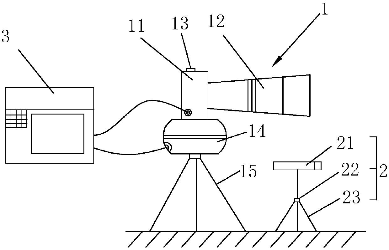
[0055] A non-contact detection system for bridge and tunnel damage, such as figure 1 As shown, it includes a non-contact detector 1, a laser projection subsystem 2, and a data processor 3 for processing measurement data and presenting data processing results. The non-contact detector 1 includes a high-definition digital camera 11, a telephoto digital camera 12, A prism-free laser range finder 13, a digitally controlled platform 14 and a support 15. Wherein, the telephoto digital camera 12 is connected with the high-definition digital camera 11, and is used to obtain the apparent image of the long-distance structure; the digital control pan-tilt 14 is installed under the high-definition digital camera 11, and is used for the high-definition digital camera 11 to obtain different positions of the bridge and tunnel The image and spatial angle information; the non-prism laser rangefinder 13 is used to measure the physical distance of the detected object.
[0056] The laser project...
Embodiment 2
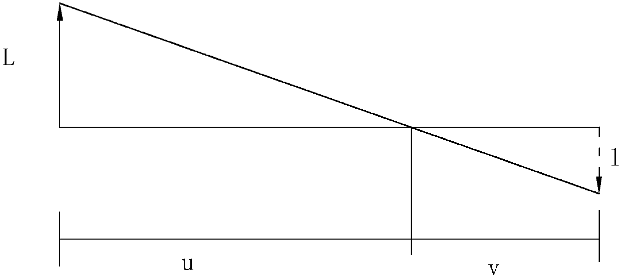
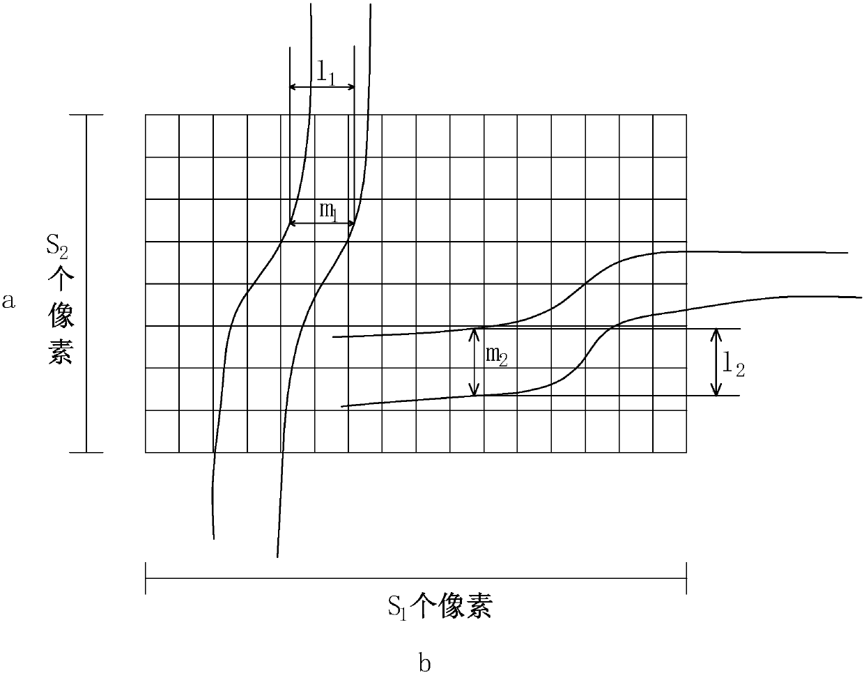
[0059] A non-contact detection method for bridge and tunnel damage, combining figure 2 , image 3 and Figure 4 As shown, using the above-mentioned bridge-tunnel disease non-contact detection system to operate, the simultaneous or separate detection of disturbances or cracks includes the following steps:
[0060] A disturbance detection steps
[0061] Step A1: Form a laser pointing point through the laser projection subsystem 2, and determine a fixed "reference point" in each preset area by means of laser pointing;
[0062] Step A2: Before loading, use the telephoto digital camera 12 and the high-definition digital camera 11 to obtain the apparent image of the long-distance structure, select the surface reference point, and obtain the physical distance of the detected object through the prismless laser rangefinder 13; 14 Adjust the image and space angle, and the camera detects multiple preset areas through the movement of the pan / tilt;
[0063] Step A3: after loading, use...
Embodiment 3
[0079] A bridge and tunnel disease non-contact detection system, the difference from embodiment 1 is that, as Figure 5 As shown, the UAV system 4 is also included, and the UAV system 4 includes a four-rotor remote control machine 41, a stabilized platform 42, a wireless image transmission communication module 43, and a high-definition camera 44; the high-definition camera 44 is installed through the stabilized platform 42 On the four-rotor remote control machine 41 , the high-definition camera 44 is electrically connected to the wireless image transmission communication module 43 , and the wireless image transmission communication module 43 and the data processor 3 perform image data transmission.
[0080] Corresponding to the above method, step 1 can be replaced by: using the unmanned aerial vehicle system 4 to obtain the physical distance and structural appearance images of the detected object. For the acquisition of images, this can be further assisted by the unmanned aeri...
PUM
 Abstract
Description
Claims
Application Information
 - R&D Engineer
- R&D Manager
- IP Professional
- Industry Leading Data Capabilities
- Powerful AI technology
- Patent DNA Extraction
Browse by: Latest US Patents, China's latest patents, Technical Efficacy Thesaurus, Application Domain, Technology Topic, Popular Technical Reports.
© 2024 PatSnap. All rights reserved.Legal|Privacy policy|Modern Slavery Act Transparency Statement|Sitemap|About US| Contact US: help@patsnap.com