Eureka AIR delivers breakthrough ideas for toughest innovation challenges, trusted by R&D personnel around the world.

Whole vehicle thermal management system of pure electric vehicle and management method

A pure electric vehicle and management system technology, applied in the field of pure electric vehicle thermal management, can solve the problems of increasing the layout pressure of the whole vehicle, waste of electric energy, and different cooling effects of the battery

Active Publication Date: 2018-06-01
ZHEJIANG UNIV
View PDF4 Cites 9 Cited by
  • Summary
  • Abstract
  • Description
  • Claims
  • Application Information

AI Technical Summary

Problems solved by technology

[0004] At present, the more common battery pack cooling method is to blow hot or cold air into the battery pack to heat or cool the battery by adjusting the fan speed and the size of the damper; The cooling effect of the cells in different areas of the battery pack is different, and the consistency of the cells is poor
In addition, the layout of fans and air ducts takes up a lot of space, which increases the layout pressure of the whole vehicle
[0005] The ambient temperature range of the electronically controlled cooling system is relatively large, but too high a temperature will shorten the service life of the motor rotor, so it needs to be forced to dissipate heat when operating in a high temperature environment; the performance of the air conditioning system directly affects the comfort of the drivers and passengers. And pure electric vehicle air conditioning operation needs to consume a lot of battery power
[0006] At present, most of the cockpit and battery pack heating systems are PTC electric heating, which has low power conversion efficiency and serious waste of power

Method used


Image

  • Whole vehicle thermal management system of pure electric vehicle and management method

Examples


Embodiment Construction

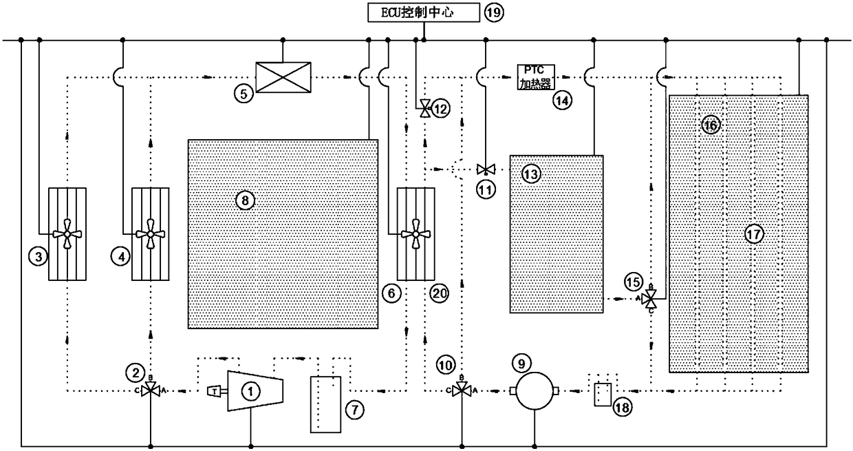
[0059] The following are specific embodiments of the present invention and in conjunction with the attached figure 1 , to further describe the technical solutions of the present invention, but the present invention is not limited to these examples.

[0060] A pure electric vehicle thermal management system, the pure electric vehicle has a heat pump air conditioning system 8, a battery pack thermal management system 16 and an electronically controlled cooling system 13; the system includes a heat pump air conditioning refrigerant liquid circulation circuit, a battery The coolant liquid circulation circuit of the thermal management system and the electronic control cooling system and the ECU control center; the two major liquid circulation circuits are coupled at the first evaporator 6 and the second evaporator 20, and the first evaporator 6 and the second evaporator The two internal pipelines for entering and exiting the liquid of the device 20 are independent, and the flow dir...


PUM


Abstract

The invention discloses a whole vehicle thermal management system of a pure electric vehicle and a management method. A heat pump type air conditioner system, a battery pack thermal management systemand an electronic control cooling system are arranged on the pure electric vehicle. The system comprises a heat pump type air conditioner refrigerant liquid circulating loop, a coolant liquid circulating loop of the battery pack thermal management system and the electronic control cooling system, and an ECU control center. The two liquid circulating loops are coupled on a first evaporator and a second evaporator, two liquid inlet and outlet internal pipelines of the first evaporator and the second evaporator are independent, and liquid flow directions are designed in a convection mode. Heat among the three sub-systems can be utilized under the condition of guaranteeing driving and riding comfort, an external cold source and sub-system heat sources are fully utilized, and the energy consumption of the whole vehicle thermal management system is reduced.

Description

technical field [0001] The invention belongs to the field of thermal management of a pure electric vehicle, and in particular relates to a thermal management system and a management method of a pure electric vehicle, which are suitable for the thermal management of a pure electric vehicle during operation. Background technique [0002] The thermal management system of a pure electric vehicle consists of three major thermal management systems: the air conditioning system, the battery thermal management system and the electronically controlled cooling system. At present, many technologies on pure electric vehicles are not yet mature, and the three major thermal management systems in pure electric vehicle models are often isolated. Pure electric vehicles only use battery packs as energy sources. During independent operation, many potential low-grade energy in the three major thermal management systems are wasted, thereby wasting a large amount of battery power. [0003] As the...

Claims


Application Information

Patent Timeline
IPC IPC(8): B60H1/00B60L11/18H01M10/613H01M10/615H01M10/617H01M10/63H01M10/633H01M10/625H01M10/653H01M10/6555H01M10/6563H01M10/6568H01M10/6571H01M10/663
CPCH01M10/613H01M10/615H01M10/617H01M10/625H01M10/63H01M10/633H01M10/653H01M10/6555H01M10/6563H01M10/6568H01M10/6571H01M10/663B60H1/00021B60H1/00278B60H1/00392B60L58/26B60L58/27B60H2001/00114H01M2220/20Y02T10/70Y02E60/10
Inventor 黄钰期梅盼陈卓烈许磊牛昊一
Owner ZHEJIANG UNIV
Why Eureka
Eureka Blog
Learn More