Backup battery cut-in and floating charge control device

A backup battery and control device technology, applied in battery circuit devices, circuit devices, battery charging management, etc., can solve the problems of large forward voltage drop of diodes, complicated circuit design, large voltage loss, etc., to reduce voltage loss, Small size, the effect of protecting circuit safety

Pending Publication Date: 2018-05-29
深圳市科卫泰实业发展有限公司
View PDF0 Cites 2 Cited by
  • Summary
  • Abstract
  • Description
  • Claims
  • Application Information

AI Technical Summary

Problems solved by technology

[0003] The traditional redundant power supply system is usually implemented by the design of isolation diodes and separate devices. The circuit design is more complicated, and because the forward voltage drop of the diode is relatively large, the power consumption of the equipment becomes the main problem under the condition of large load current.
Therefore, the traditional redundant power supply system has problems such as large power consumption, large voltage loss, complex circuit, serious heat generation, and large footprint.

Method used


Image

  • Backup battery cut-in and floating charge control device
  • Backup battery cut-in and floating charge control device
  • Backup battery cut-in and floating charge control device

Examples


Embodiment Construction

[0025] In order to make the object, technical solution and advantages of the present invention clearer, the present invention will be further described in detail below in conjunction with the accompanying drawings and embodiments. It should be understood that the specific embodiments described here are only used to explain the present invention, not to limit the present invention.

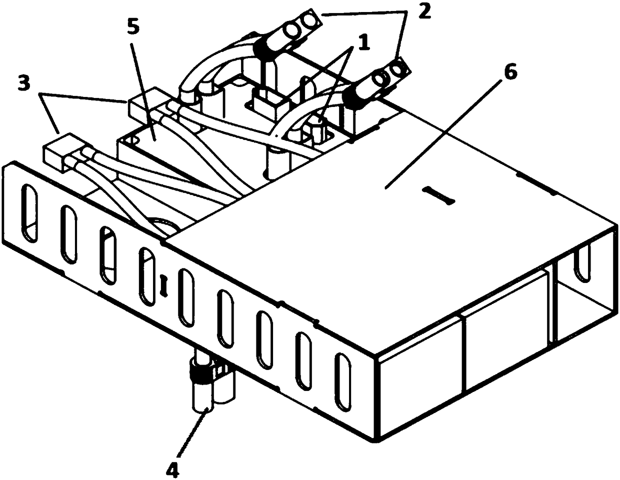
[0026] see figure 1 as shown, figure 1 It is a schematic structural diagram of the cut-in and float charge control device for the backup battery of the present invention. This embodiment provides a backup battery cut-in and floating charge control device, which is installed on a tethered drone and includes a backup battery box 6 and an onboard power supply (not shown). The onboard power supply is connected to the ground terminal power supply of the tethered drone through the tethered cable, and the ground terminal power supply supplies power to the load of the tethered drone through the onboard p...


PUM


Abstract

The invention provides a backup battery cut-in and floating control device which is installed on a mooring unmanned aerial vehicle, and the control device comprises a backup battery box and an airborne power supply, a backup battery and a backup battery switching box are installed in the backup battery box, a backup battery switching board is installed in the backup battery switching box, a backupbattery switching circuit and a backup battery floating charge control circuit are arranged on the backup battery switching board. Compared with the prior art, the equipment efficiency can be improved, the power consumption, the heat consumption and the voltage loss are reduced, and the area of the PCB is reduced; the power conversion efficiency can be up to 96%, and the control device has the advantages of being high in integration level, small in size, simple in peripheral circuit, the power consumption can be effectively reduced, and the functions of input overvoltage and undervoltage locking, output overvoltage protection, over-temperature protection, and over-current protection can be realized.

Description

technical field [0001] The invention relates to the power supply technology of a tethered unmanned aerial vehicle, in particular to a backup battery cut-in and floating charge control device for a tethered unmanned aerial vehicle. Background technique [0002] The ground terminal power supply of the tethered UAV supplies power to the tethered UAV system through the tethered cable, so that the UAV can hover in the air for a long time to complete the aerial work. When the power supply of the ground terminal of the tethered UAV system is abnormal, the design of parallel power supply and battery can realize redundancy, and the system can immediately switch to the backup battery power supply to ensure the safe flight of the tethered UAV. [0003] The traditional redundant power supply system is usually implemented by the design of isolation diodes and separate devices. The circuit design is more complicated, and because the forward voltage drop of the diode is relatively large, t...

Claims


Application Information

Patent Timeline
IPC IPC(8): H02J9/06H02J7/00H01M10/42
CPCH02J7/0022H01M10/4207H02J7/0013H02J7/007H02J9/061Y02E60/10
Inventor 程薪龙
Owner 深圳市科卫泰实业发展有限公司
Why Eureka
Try Eureka