High-efficiency heat accumulation type tube heating furnace system

A tubular heating furnace and regenerative technology, applied in the direction of improving energy efficiency, lighting and heating equipment, furnaces, etc., can solve the problems of long service life, low comprehensive investment, small footprint of tubular furnaces, etc., and achieve automation The effect of high level and reduced system investment

Inactive Publication Date: 2018-05-25
湖北鑫固久技术装备有限公司
View PDF7 Cites 2 Cited by
  • Summary
  • Abstract
  • Description
  • Claims
  • Application Information

AI Technical Summary

Problems solved by technology

[0005] However, although the existing tubular heating furnaces add some pre-heaters and heat exchangers in the utilization of exhaust waste heat or set up a turbulent flow heat exchange chamber and a heat exchange chamber between the combustion chamber and the heat exchange chamber, they all For indirect heat exchange, the heat exchange area is limited, the pipeline is easy to scale, and the heat energy utilization rate is not high. The regenerative tubular heating furnace uses the regenerator to absorb the waste heat of the exhaust gas to directly heat the combustion air, direct heating, and adopts two-way double-circuit Regenerator, stable combustion, high utilization rate of heat energy, small footprint per unit load tube furnace, low comprehensive investment and long service life

Method used


Image

  • High-efficiency heat accumulation type tube heating furnace system

Examples


Embodiment Construction

[0025] The technical scheme of the present invention will be further described below in conjunction with the drawings and embodiments.

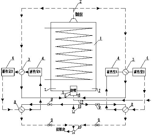
[0026] With reference to the drawings, the present invention is a high-efficiency regenerative tubular heating furnace system, which includes a 1-tube furnace body, a 2-chimney, a 3-high temperature four-way reversing valve, a 4-regenerator, and a 5-burner. 6-small fire detector, 7-large fire detector, 8-low temperature four-way reversing valve, 9-distribution valve, 10-induced draft fan, 11-blower, 12-gas inlet; tube heating furnace system burns through gas Combustion and combustion air are mixed and combusted at the burner 5, heated by the heating medium in the tube furnace body 1, and the generated tail gas is passed from the chimney 2 through the high-temperature four-way reversing valve 3 through the regenerator 4 and the low-temperature four-way reversing valve 8. Discharged by the induced draft fan 11, the combustion-supporting air passes...


PUM


Abstract

The invention discloses a high-efficiency heat accumulation type tube heating furnace system and relates to the technical field of tube heating furnaces, energy conservation and emission reduction. The high-efficiency heat accumulation type tube heating furnace system is provided for solving the problems that an existing tube heating furnace is low in thermal efficiency, short in service life, poor in stability and high in system investment. The high-efficiency heat accumulation type tube heating furnace system comprises a tube furnace body, a burner nozzle, heat accumulation chambers, four-way reversing valves, an air blower, induced draft fans, air distribution valves, flame detectors and other devices. The air blower periodically blows combustion air into the left heat accumulation chamber and the right heat accumulation chamber at indoor temperature correspondingly and conducts heat exchange with the corresponding heat accumulation chambers to heat combustion air to 300 DEG C or above. Tail gas periodically passes through the heat accumulation chambers correspondingly and conducts heat exchange with the corresponding heat accumulation chambers, then the temperature of the tailgas is gradually reduced to about 130 DEG C, and then the tail gas is discharged through the induced draft fans. The air and the tail gas are periodically exchanged in the left and right heat accumulation chambers correspondingly to achieve high-efficiency and stable burning. Meanwhile, a traditional convection section is omitted, the exhaust gas temperature is reduced, and the thermal efficiencyis improved. Accordingly, the comprehensive investment of the tube furnace is minimized, and the service life of the tube furnace is prolonged.

Description

Technical field [0001] The invention discloses a high-efficiency regenerative tubular heating furnace system, which relates to the technical field of tubular heating furnaces and energy saving and emission reduction, and specifically discloses an efficient and stable two-way double-circuit regenerative tubular heating furnace. Background technique [0002] Tubular heating furnaces are process heating furnaces widely used in petroleum refining, petrochemical and coal chemical industries. The medium to be heated in the tube is gas or liquid, and they are all flammable and explosive materials. The operating conditions are harsh. At the same time, the long-term operation is continuous, and the heating method is directly exposed to fire. The exhaust gas temperature of the tubular heating furnace can be lowered to about 100°C to achieve partial condensation of the acid steam in the flue gas, and while recovering the low-temperature sensible heat of the flue gas, it can also recover par...

Claims


Application Information

Patent Timeline
IPC IPC(8): F27B17/00F27D17/00F23L15/00
CPCF23L15/00F27B17/00F27D17/004F27D2017/007Y02E20/34Y02P10/25
Inventor 陈云斌陈天余建华陈志勋王宏成
Owner 湖北鑫固久技术装备有限公司
Why Eureka
Try Eureka