Lift axle control unit for a motor vehicle

A technology of control unit and electronic control unit, which is applied in the lift shaft suspension system and the field of vehicles and commercial vehicles. It can solve the problems of design complexity, manufacturing cost, excessive air, and high manufacturing cost, and achieve the effect of reducing hardware cost.

Active Publication Date: 2016-03-09
WABCO TVS (INDIA) LIMITED
View PDF6 Cites 1 Cited by
  • Summary
  • Abstract
  • Description
  • Claims
  • Application Information

AI Technical Summary

Problems solved by technology

[0010] One disadvantage of these prior art lift shaft control valves is the high cost of manufacture due to the separate cast valve bodies for the individual valves (lift shaft control valve and relay valve) and the pipe connection
[0011] Another disadvantage of the known technology is that the separate exhaust ports of the valve have to be individually protected from water and dust
[0012] Another disadvantage of the known technology is the direct execution of the control of the external relay valve connected to the suspension bellows, without damping
More air consumption due to frequent discharge of air from the suspension bellows when the vehicle passes over bumpy road conditions
[0013] Another disadvantage of the lift shaft control valves of the known art can be seen from the fact that load detection is performed by means of a double throw pressure switch
[0016] The drawbacks of this system are still the complexity of its design and the cost of manufacturing

Method used


Image

  • Lift axle control unit for a motor vehicle
  • Lift axle control unit for a motor vehicle
  • Lift axle control unit for a motor vehicle

Examples


Embodiment Construction

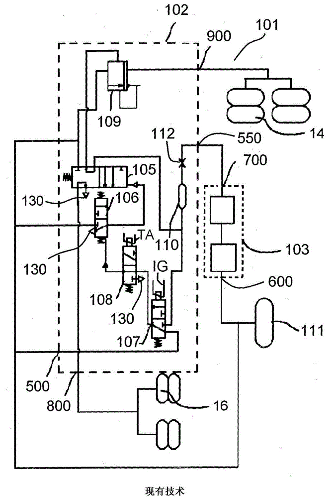
[0040] refer to figure 1 , a prior art lift axle control system 101 includes two devices, both shown in dashed lines: a lift axle control valve 102 and a load sense valve 103 . Furthermore, a pressurized air container 111 , a suspension bellows 14 and a lifting bellows 16 are provided. The lift shaft control valve 102 comprises a spool valve 105, a differential pressure valve 106, a first solenoid valve 107 for receiving an ignition signal IG, a second solenoid valve 108 for receiving an electrical override signal TA and for enabling manual override , relay valve 109, damping container 110 and small hole (throttle valve) 112.

[0041] The delivery pressure 700 of the load sense valve 103 is given as a control input 550 to the lift axle control valve 102 . Control input 550 is then given to damping container 110 through aperture 112 . The control pressure from the damping container 110 is given to the differential pressure valve 106 through the first solenoid valve 107 and t...


PUM


Abstract

The invention refers to a lift axle control unit (1) for a lift axle suspension system (30) of a vehicle (1000), said lift axle control unit (1) comprising at least: an electronic control unit (4) receiving at least a first electric input signal (S1) and a position indicating signal (S4), at least one supply input port (100) to be connected to a pressure reservoir (2), a first delivery port (220) to be connected to at least one suspension bellow (14) and a second delivery port (250) to be connected to at least one lift bellow (16), a load detection valve (3) being connectable to load variable parts (1010) of said vehicle (1000) and delivering an pressure output signal (p3) in dependence of an axle load of the vehicle (1000), a first relay valve (6) connected to said first delivery port (220) for feeding said suspension bellow (14), a second relay valve (7) connected to said second delivery port (250) for feeding at least one lift bellow (16), a solenoid valve (5) for receiving an electric control signal (S5) from said electronic control unit (4) and for connecting said load detection valve (3) to said first and second relay valve (6, 7) or separating it from said first and second relay valve (6, 7) in dependence of said electric control signal (S5).

Description

technical field [0001] The invention relates to a lift axle control unit to be used in a lift axle suspension system of a commercial vehicle, furthermore to a lift axle suspension system comprising such a lift axle control unit and to a vehicle, in particular A commercial vehicle including such a lift axle suspension system. Background technique [0002] Lift axle suspension systems for commercial vehicles typically include suspension bellows (like other axles) for damping and for adjusting the distribution of axle loads between the axles, and one or more Bellows are lifted to free the wheels of the lift axle from the ground; pneumatic valves for controlling these bellows are also provided. [0003] Lift axle suspension systems in commercial vehicles are capable of the following functions: [0004] - automatically raises or lowers the lift axle depending on the vehicle load state, [0005] - For better traction and maneuverability of the vehicle, over-slack to raise the l...

Claims


Application Information

Patent Timeline
IPC IPC(8): B60G17/052B60G17/056
CPCB60G17/0526B60G2204/4702B60G2300/02B60G2600/02B60G2600/604
Inventor 加内萨穆尔蒂·阿鲁穆加姆森什尔纳坦·阿鲁纳恰拉姆乔宾·乔瓦图库内尔纳拉亚南·斯里尼瓦桑塞尔瓦玛尼·孙达拉玛哈林甘萨胡尔·哈米德·塔梅斯登约翰·卢卡斯
Owner WABCO TVS (INDIA) LIMITED
Why Eureka
Try Eureka