Eureka AIR delivers breakthrough ideas for toughest innovation challenges, trusted by R&D personnel around the world.

Compressor unit, heat source unit, and air conditioner

a compressor unit and heat source technology, applied in the field of compressor units, heat source units, air conditioners, can solve the problems of perceived disadvantage, noise that may be perceived disturbing in outdoor units, etc., and achieve the effects of increasing efficiency, increasing installation costs, and increasing costs

Inactive Publication Date: 2018-05-10
DAIKIN IND LTD +1
View PDF9 Cites 1 Cited by
  • Summary
  • Abstract
  • Description
  • Claims
  • Application Information

AI Technical Summary

Benefits of technology

The present invention aims to solve the problem of integrating a sub-cooling section into a heat source unit, which requires more piping and higher installation costs due to the increased distance between the compressor unit and the heat source heat exchanger unit. The invention proposes a compressor unit and a heat source unit with a minimum of piping, particularly for gaseous refrigerant, to reduce installation costs and ensure ease of installation.

Problems solved by technology

This, however, has under certain circumstances being perceived disadvantageous from an aesthetical point of view.
One negative aspect is that the outdoor unit produces noises which may be perceived disturbing by individuals inside the building.
A second negative aspect is installation and maintenance, because the outdoor unit is relatively heavy and because of its construction requires a relatively large installation space with respect to its height.

Method used


Image

  • Compressor unit, heat source unit, and air conditioner
  • Compressor unit, heat source unit, and air conditioner
  • Compressor unit, heat source unit, and air conditioner

Examples


Embodiment Construction

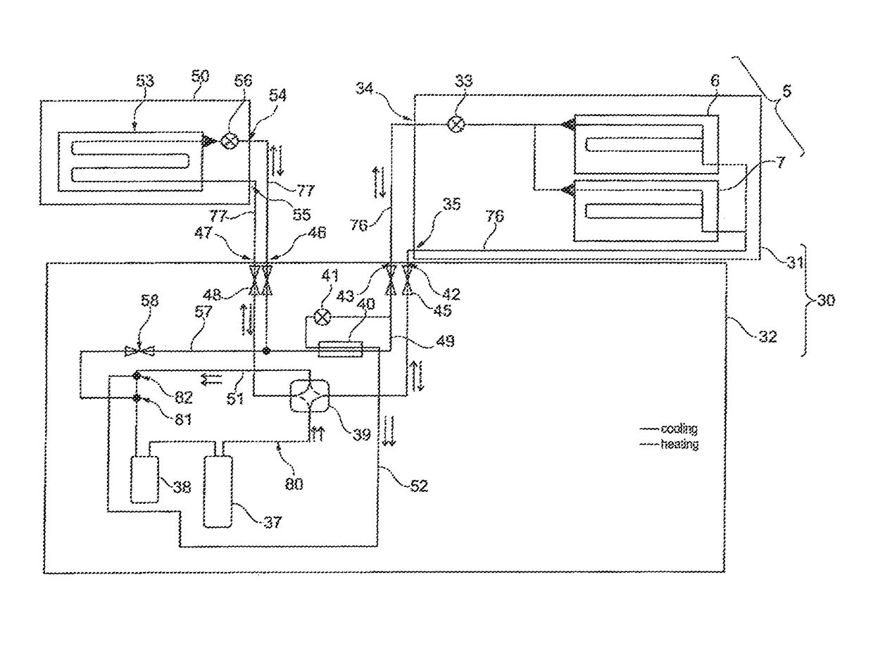
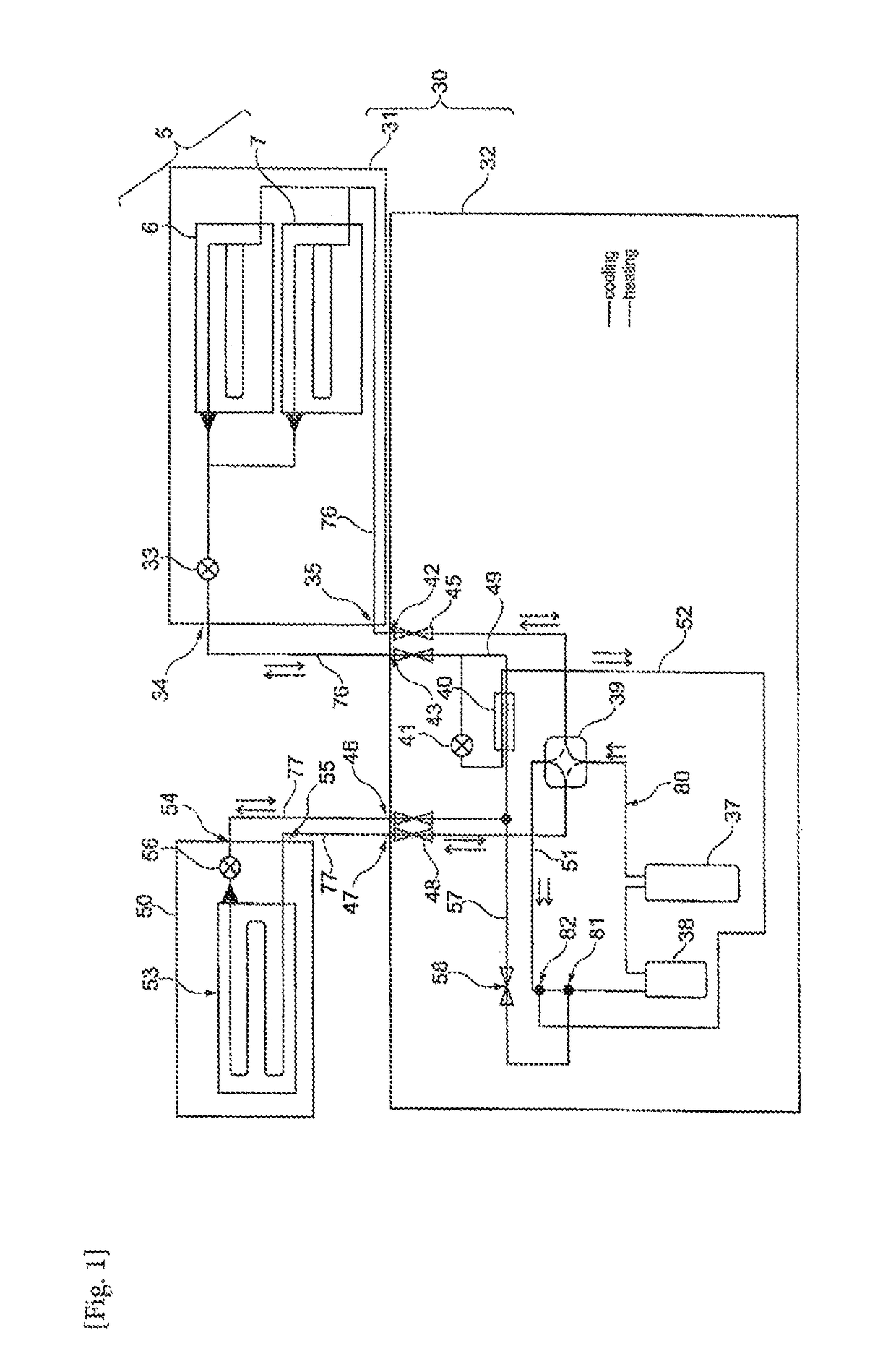
[0024]FIG. 1 shows the circuit diagram of an air conditioner. The air-conditioner has a heat source unit 30 comprising a heat source heat exchanger unit 31 and a compressor unit 32.

[0025]The heat source heat exchanger unit 31 comprises a heat exchanger 5 which consists of an upper heat exchanger element 6 and a lower heat exchanger element 7 which are positioned relative to each other to form the shape of a “V” in a side view or cross sectional view (see FIG. 5). The heat source heat exchanger unit 31 further comprises the main expansion valve 33 of the refrigerant circuit. As becomes apparent from FIG. 1, the entire amount of refrigerant contained in the circuit also passes the main expansion valve 33 during cooling. In other words, the entire amount of refrigerant delivered or supplied from the compressor 37 flows through the main expansion valve 33 during cooling.

[0026]The heat source heat exchanger unit is also shown in more detail in FIGS. 3 and 5.

[0027]FIGS. 3 and 5 show a hea...


PUM


Abstract

A compressor unit for an air conditioner includes a compressor disposed in a first casing, and first and second heat source heat exchanger unit ports configured to connect the compressor unit to a heat source heat exchanger of a heat source heat exchanger unit of the air conditioner, the heat source heat exchanger being disposed in a second casing separate from the first casing and being configured to exchange heat with a heat source, first and second indoor unit ports configured to connect the compressor unit to an indoor heat exchanger of at least one indoor unit of the air conditioner, a first refrigerant piping fluidly connecting the first heat source heat exchanger unit port and the first indoor unit port, and a sub-cooling heat exchanger disposed inside the first casing and fluidly connected to the first refrigerant piping for heat transfer with the refrigerant to be flown through the first refrigerant piping.

Description

TECHNICAL FIELD[0001]The present invention relates to air conditioners and particularly air conditioners using outside air or circulating water as heat source. Such air-conditioners may as well be called heat pumps. Further, the air-conditioners may be used for cooling and / or heating of a space to be conditioned. More particularly, the present invention relates to a compressor unit for such an air conditioner and a heat source unit of such an air conditioner.BACKGROUND ART[0002]Generally speaking, air-conditioners consist of one or more outdoor units and one or more indoor units connected via a refrigerant piping. The outdoor and indoor units each comprise a heat exchanger for, on the one hand, exchanging heat with the heat source and, on the other hand, exchanging heat with the space to be conditioned. Outdoor units of air-conditioners are in most cases installed outside a building for example on the roof or at the facade. This, however, has under certain circumstances being percei...

Claims


Application Information

Patent Timeline
IPC IPC(8): F24F1/08F24F1/14F24F1/26F25B13/00F25B30/02
CPCF24F1/08F24F1/14F24F1/26F25B13/00F25B30/02F25B2400/13F25B2500/12F25B2313/0253F25B2313/0233
Inventor BAETENS, FRANSPIRMEZ, PIETERVANOOTEGHEM, JAN
Owner DAIKIN IND LTD
Why Eureka
Eureka Blog
Learn More