
Rotor of double-cone and parallel-flow horizontal spiral centrifuge

A decanter centrifuge and rotor technology, applied to centrifuges, centrifuges with rotating drums, etc., can solve the problems of polluted water, secondary pollution, and increased use costs, so as to facilitate rapid liquid drainage and increase centrifugation Time, the effect of increasing the stroke

Pending Publication Date: 2018-05-25
ZHEJIANG SANTUO HEAVY IND TECH
View PDF7 Cites 0 Cited by
  • Summary
  • Abstract
  • Description
  • Claims
  • Application Information

AI Technical Summary

Problems solved by technology

The existing rotor structure cannot meet these requirements, and the rotor structure must be improved
[0003] On the other hand, most of the existing centrifuges must use flocculants to ensure the effective separation of engineering sewage
However, the chemical components contained in the flocculant will pollute the water body, thereby causing secondary pollution and increasing the cost of use. How to improve the separation effect by increasing the separation factor or increasing the sedimentation depth is also the main development direction for improving the performance of decanter centrifuges.

Method used


Image

  • Rotor of double-cone and parallel-flow horizontal spiral centrifuge
  • Rotor of double-cone and parallel-flow horizontal spiral centrifuge
  • Rotor of double-cone and parallel-flow horizontal spiral centrifuge

Examples


Embodiment Construction

[0023] In order to make the technical problems, technical solutions and beneficial effects to be solved by the present invention clearer, the present invention will be further described in detail below in conjunction with the accompanying drawings and embodiments. It should be understood that the specific embodiments described here are only used to explain the present invention, not to limit the present invention.

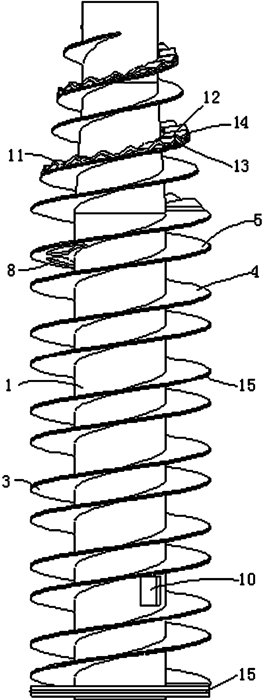
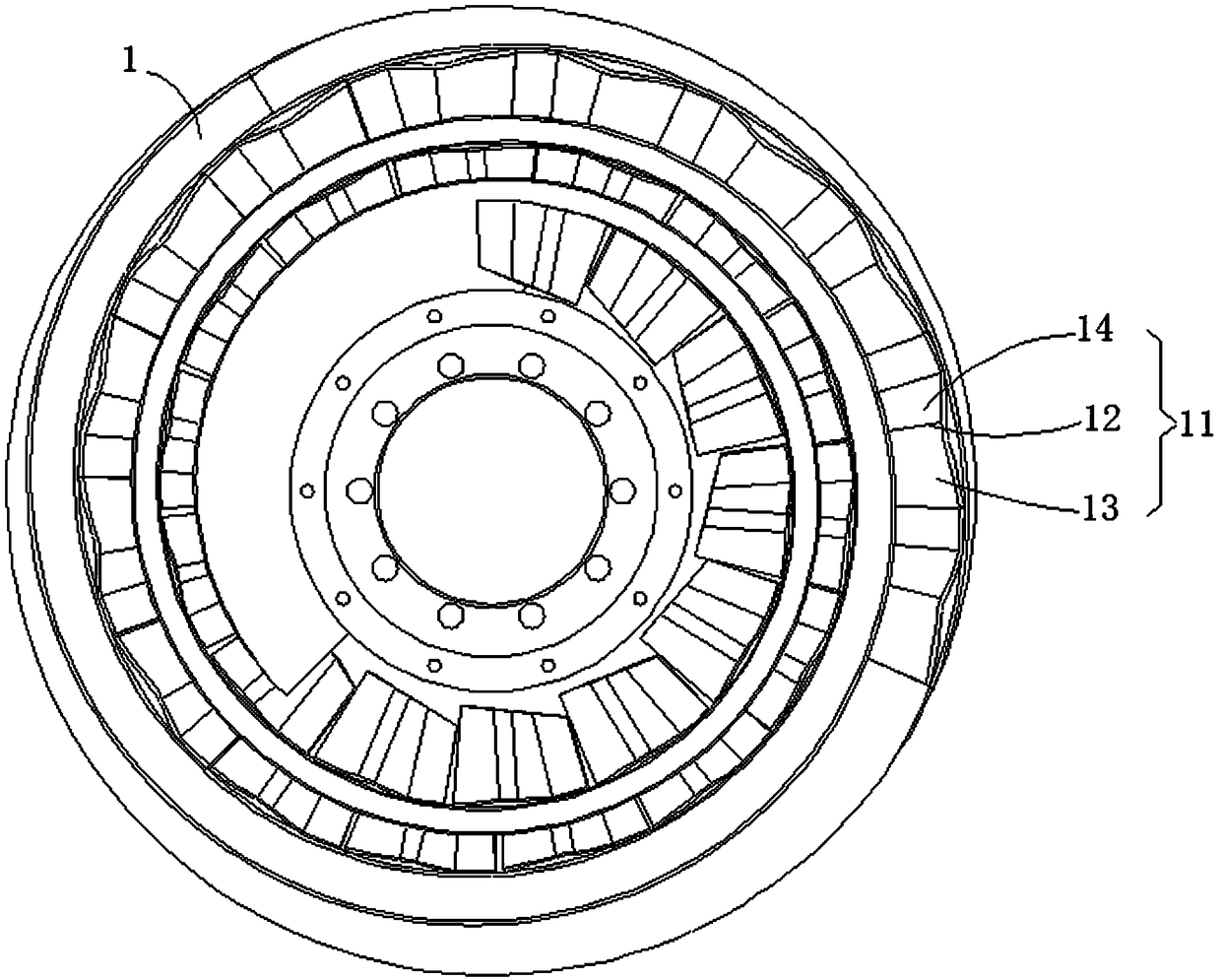
[0024] Please also refer to figure 1 , figure 2 as well as image 3 As shown, the preferred embodiment of the rotor of the double-cone parallel-flow decanter centrifuge of the present invention, the rotor 1 is arranged in the drum 2 of the double-cone parallel-flow decanter centrifuge, and double rows of helical blades are arranged on the surface of the rotor 1 3.

[0025] The drum 2 and the rotor 1 include a small end and a large end, and the transition between the large and the small ends is through a conical portion. The differential 2 drives the drum 2 and ...


PUM


Abstract

The invention relates to a rotor of a double-cone and parallel-flow horizontal spiral centrifuge. The rotor is arranged in a drum of the double-cone and parallel-flow horizontal spiral centrifuge, double rows of helical blades are arranged on the surface of the rotor and form a raw material channel and a liquid draining channel, a plurality of liquid return holes are formed in the double rows of helical blades, the raw material channel and the liquid draining channel communicate with each other only at the liquid return holes, a feed pipe is arranged in the rotor, a plurality of feed holes which communicate with the feed pipe are further formed in the rotor, and the plurality of feed holes communicate with the raw material channel; a plurality of residue loosening structures are arranged on the surfaces of the double rows of helical blades of the raw material channel, wavy protrusions which are higher than the surfaces of the double rows of helical blades are arranged on the residue loosening structures, and the radial distribution direction of the wavy protrusions of the residue loosening structures along the rotor is perpendicular to the residue discharge direction. According tothe rotor, effective solid-liquid separation can be performed on engineering sewage, the separating effect is good, and the problem that sludge in the rotor needs to be cleaned with clear water beforean existing centrifuge is shut down is solved.

Description

technical field [0001] The invention relates to solid-liquid separation equipment, in particular to a rotor of a double-cone parallel-flow decanter centrifuge. Background technique [0002] As a general-purpose machine, decanter centrifuges are widely used in various industries. With the changes in the structural design of the centrifuge and the continuous optimization of parameters, its separation quality and production capacity are getting better and better, far exceeding the previous design level. However, high separation efficiency (high dryness of slag and high clarity of clear liquid) and low energy consumption are contradictory. Therefore, research and optimization of special structures are the main development direction to further improve the performance of decanter centrifuges. The rotor of the decanter centrifuge is one of the key components, and the structure of the rotor directly affects the performance of the decanter centrifuge. The existing rotor structure...

Claims


Application Information

Patent Timeline
Patent Type & Authority Applications(China)
IPC IPC(8): B04B1/20
CPCB04B1/20B04B2001/2041
Inventor 梁利华贾高顺潘柏松林金伟张福增应忠初
Owner ZHEJIANG SANTUO HEAVY IND TECH
Learn More