


Quick Research
Generate reliable direction feasibility study reports for your R&D in just a few steps.

Technical Q&A
Discover and master advanced knowledge NOW. Basics, ideas, possibilities, all at once.

Find Solutions
As an expert in R&D theories, this can generate solutions to your technical problems instantly.

Evaluate Feasibility
Analyze your overall solution with one click, know your potential R&D risks in advance.

Monitor Landscape
Get weekly tech updates, stay abreast of the latest tech innovations and key insights.
motor
A technology of motors and coils, applied in the direction of winding insulation materials, etc., can solve problems such as partial discharge and reduction of motor insulation performance, and achieve the effect of sharing voltage reduction
- Summary
- Abstract
- Description
- Claims
- Application Information
AI Technical Summary
Problems solved by technology
Method used
Image

Examples
Embodiment approach 1
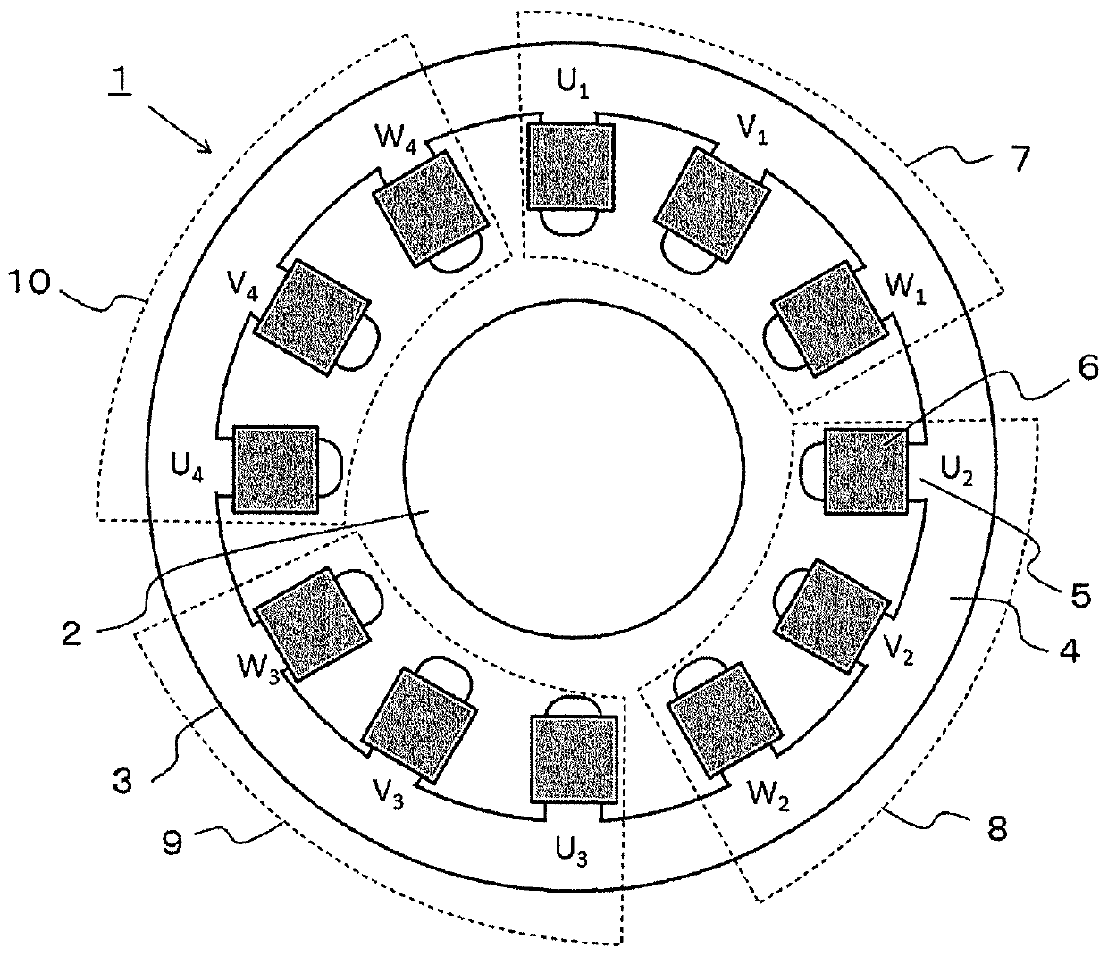
[0027] figure 1 It is a schematic diagram of the motor concerning Embodiment 1 for carrying out this invention. exist figure 1 Among them, the motor 1 includes a rotor 2 and a stator 3 . The stator 3 includes a cylindrical core 4 , teeth 5 protruding from the core 4 to the inner peripheral side, and hollow molded coils 6 inserted into the teeth 5 . The motor 1 in this embodiment is a Y-connected concentrated winding motor with three phases and four coils connected in series. The coils on the power supply side are U1, V1, and W1, and the coils on the neutral point side are U2, V2, and W2, U3, V3, and W3, and U4, V4, and W4. Hereinafter, the power supply side coil is referred to as the first coil 7 , and the neutral point side is referred to as the second coil 8 , the third coil 9 , and the fourth coil 10 . These coils are all constituted by molded coils 6 .
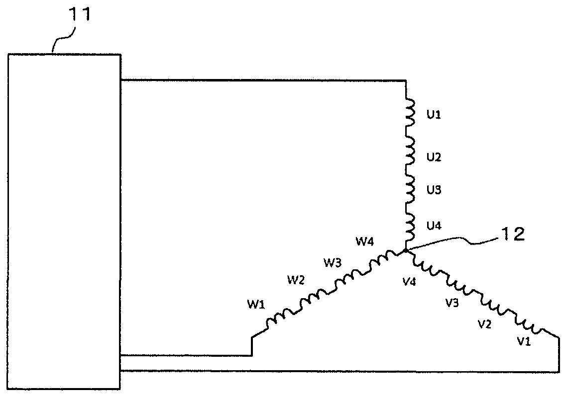
[0028] figure 2 It is an equivalent circuit diagram of the motor 1 of this embodiment. exist figure 2 In , t...
Embodiment approach 2
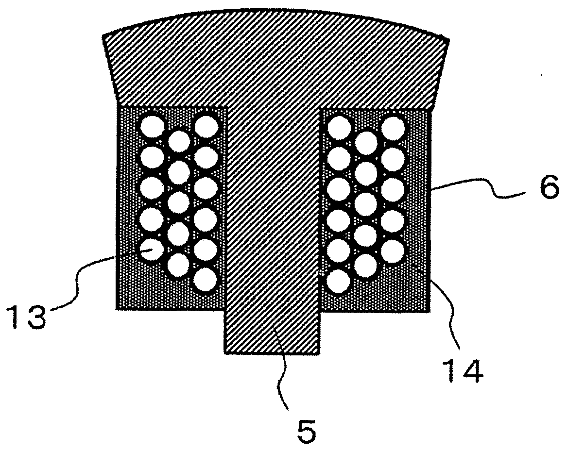
[0046] Figure 7 It is a cross-sectional view of a molded coil according to Embodiment 2 for carrying out the present invention. The structure of the motor in this embodiment is the same as that of Embodiment 1. figure 1 The construction of the motor shown in is the same. exist Figure 7 middle, Figure 7 (a) is a cross-sectional view of the molded coil of the coil on the power feeding part side, Figure 7 (b) is a cross-sectional view of a molded coil of a coil located at a position other than the power feeding part side. Will Figure 7 The dielectric constant of the molding material of the first coil disposed on the feeding part side shown in (a) is ε 1 ,Will Figure 7 The dielectric constant of the molding material of the other coils shown in (b), that is, the second coil, the third coil, and the fourth coil is set to ε 2 . In the motor of this embodiment, so that ε 1 greater than ε 2 The way to select the molding material.
[0047] and, will Figure 7 The thi...
Embodiment approach 3
[0050] Figure 8 It is a schematic diagram of the motor concerning Embodiment 3 for carrying out this invention. The motor 1 in the present embodiment is a Y-connected concentrated winding motor with three phases and four coils connected in series, as in the first embodiment. The coils on the feeder side of each phase are U1, V1, and W1, and the coils on the neutral point side are U2, V2, and W2, U3, V3, and W3, and U4, V4, and W4.
[0051] In this embodiment, the first coil 7 ( U1 , V1 , and W1 ) serving as the power feeding part side coil is composed of the molded coil 6 molded from a molding material similarly to the first embodiment, and the other second coils Coil 8 (coils U2 , V2 , and W2 ), third coil 9 ( U3 , V3 , and W3 ), and fourth coil 10 ( U4 , V4 , and W4 ) are constituted only by winding 13 . That is, with respect to the coils other than the coils located on the power feeding part side, the surroundings of the windings are air with a dielectric constant of 1. ...
PUM
 Abstract
Description
Claims
Application Information
 - R&D Engineer
- R&D Manager
- IP Professional
- Industry Leading Data Capabilities
- Powerful AI technology
- Patent DNA Extraction
Browse by: Latest US Patents, China's latest patents, Technical Efficacy Thesaurus, Application Domain, Technology Topic, Popular Technical Reports.
© 2024 PatSnap. All rights reserved.Legal|Privacy policy|Modern Slavery Act Transparency Statement|Sitemap|About US| Contact US: help@patsnap.com