
Measurement device and measurement method for magnetic field generated by high-density plasma

A plasma and magnetic field measurement technology, which is applied to the size/direction of the magnetic field and the use of magneto-optical equipment for magnetic field measurement. It can solve problems such as information interference, and achieve the effect of improving accuracy and reducing impact.

Active Publication Date: 2018-05-15
SHANGHAI INST OF OPTICS & FINE MECHANICS CHINESE ACAD OF SCI
View PDF5 Cites 5 Cited by
  • Summary
  • Abstract
  • Description
  • Claims
  • Application Information

AI Technical Summary

Problems solved by technology

[0013] The object of the present invention is to provide a measuring device and method for measuring the magnetic field generated by high-density plasma driven by strong laser, which can realize the two-dimensional self-generated magnetic field with intensity up to megagauss in laser high-density plasma interaction The ultra-fast measurement of the distribution solves the problem that the scattered light of the main pulse will interfere with the information carried by the probe light, and obtains the evolution information of the magnetic field with a time scale of picoseconds over time

Method used


Image

  • Measurement device and measurement method for magnetic field generated by high-density plasma
  • Measurement device and measurement method for magnetic field generated by high-density plasma
  • Measurement device and measurement method for magnetic field generated by high-density plasma

Examples


Embodiment Construction

[0037] The present invention will be further described below in conjunction with specific embodiments and drawings, but the protection scope of the present invention should not be limited by this.

[0038] See first figure 1 , figure 1 It is a schematic diagram of the structure of the magnetic field measuring device of the present invention. It can be seen from the figure that the measuring device for the magnetic field generated by the high-density plasma driven by the strong laser of the present invention includes a first convex lens 9 and a second convex lens 10 to form a 4f system, a quarter wave plate 11, a polarization beam splitter 12, The first polarizer 13, the second polarizer 15, the first CCD camera 14, the second CCD camera 16, the first computer terminal 17, and the second computer terminal 18,

[0039] Along the output light direction are the first convex lens 9, the second convex lens 10, the quarter wave plate 11, and the polarization beam splitter 12, which divi...


PUM


Abstract

The invention provides a measurement device and a measurement method for a magnetic field generated by the strong laser driven high-density plasma. The device comprises a 4f system formed by two convex lenses, a quarter-wave plate, a polarization beam splitter, a polarizer, a CCD camera and a computer terminal. The invention discloses an ultrafast noncontact magnetic field measurement method. Withapplication of the device and the method, the problem that the scattered light of the main pulse interferes the information carried by the probe light in the experiment of measuring the magnetic field generated by the strong laser driven high-density plasma through the Farley's rotation effect and the pump probe method can be solved so that the magnetic field measurement accuracy can be enhanced.

Description

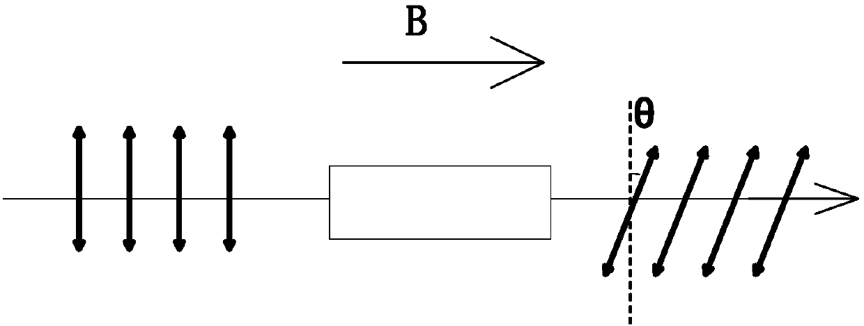
Technical field [0001] The invention relates to a magnetic field, in particular to a magnetic field measuring device and a measuring method used for high-density plasma driven by a strong laser. Background technique [0002] The fast ignition scheme in inertial confinement fusion has aroused the interest of researchers from all over the world in studying the propagation of relativistic strong lasers in plasma. An important factor in the complex interaction between laser and plasma is the existence of a strong self-generated quasi-static magnetic field. It is because the strong laser drives fast electrons to generate a strong current in the propagation direction, and then generates a strong magnetic field. Such a strong magnetic field can affect the propagation of the laser and the transport of the fast electrons. In addition to the mass dynamic and relativistic self-focusing effect, it also It will cause the magnetic focusing effect and produce various plasma instabilities. For e...

Claims


Application Information

Patent Timeline
Patent Type & Authority Applications(China)
IPC IPC(8): G01R33/032
CPCG01R33/032
Inventor 周楚亮田野曾雨珊白亚锋周诗怡李中鹏刘建胜
Owner SHANGHAI INST OF OPTICS & FINE MECHANICS CHINESE ACAD OF SCI
Learn More