Sealing device of blast furnace planetary reducer

A planetary reducer and sealing device technology, which is applied in the direction of engine sealing, transmission parts, mechanical equipment, etc., can solve the problems of ignorance and misunderstanding of the transmission principle, so as to improve the anti-deformation ability, reduce bending, prevent deformation or The effect of destruction

Inactive Publication Date: 2018-05-11
HEILONGJIANG HENGNENG SELF CONTROL TECH CO LTD
View PDF0 Cites 0 Cited by
  • Summary
  • Abstract
  • Description
  • Claims
  • Application Information

AI Technical Summary

Problems solved by technology

[0002] The blast furnace planetary reducer is the core component of the blast furnace bellless top material distribution equipment. The design and layout of its transmission structure, the design of the sealing device, the control of processing and manufacturing quality and the use and maintenance of the site directly affect the use effect and life of the reducer. ;The blast furnace planetary reducer and the transmission gearbox constitute the blast furnace bellless top distribution device. To understand the transmission principle of the planetary reducer, it is necessary to fully understand the overall structure of the distribution device; the distribution device requires that the distribution chute can realize three kinds of movements : The chute rotates alone, the chute tilts alone, and the chute rotates and tilts at the same time; Shougang has designed and manufactured this distribution device for many years, and the equipment can fully meet this functional requirement; however, at the blast furnace site, many production operators and equipment maintenance personnel Due to the lack of understanding of the transmission principle of this kind of material distribution device, some misunderstandings are often caused in the process of equipment maintenance

Method used


Image

  • Sealing device of blast furnace planetary reducer

Examples


Embodiment Construction

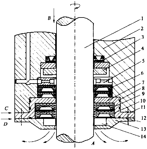
[0011] Such as figure 1 As shown, the sealing device of the blast furnace planetary reducer of the present invention includes a rotating arm shaft 1; a rotating arm support 2 is provided on the outside of the rotating arm shaft 1; a gland 13 is installed at the end of the rotating arm support 2; The boom frame 2 is sequentially installed on the outer side of the boom shaft 1 with a J-type oil seal 3, a magnetic oil seal 4, an oil guide ring 5, a composite oil seal 6, a sealing sleeve 7, a high pressure oil seal 9 and a packing 10 from top to bottom; An O-shaped sealing ring 8 is provided on the sealing sleeve 7; an asbestos gasket 11 is provided on the outside of the sealing sleeve 7; a sealing ring 12 is installed between the boom bracket 2 and the gland 13.

[0012] An oil bearing or copper sleeve 14 is installed on the gland 13.

[0013] A steel gasket (not shown) is installed between the high pressure resistant oil seal 9 and the packing 10.

[0014] The inner diameter of the s...


PUM


Abstract

The invention discloses a sealing device of a blast furnace planetary reducer. The sealing device of the blast furnace planetary reducer comprises a rotary arm shaft, wherein a rotary arm frame is arranged on the outer side of the rotary arm shaft; a gland is arranged on the end part of the rotary arm frame; a J type oil seal, a magnetic oil seal, an oil guiding ring, a composite oil seal, a sealsleeve, a high-temperature-resistant oil seal and a filter are sequentially arranged on the outer side of the rotary arm shaft on the rotary arm frame from top to bottom; an O type seal ring is arranged on the seal sleeve; an asbestos pad is arranged on the outer side of the seal sleeve; and a seal ring is arranged between the rotary arm frame and the gland. According to the sealing device of theblast furnace planetary reducer provided by the invention, the non-deformability of the oil seal is improved, pressure-bearing performances of an oil-seal edge and an oil-seal waist are greatly improved, the bending of the rotary arm shaft due to the action of a radial force of a gear is greatly reduced, the oil-seal edge is prevented from deforming or being damaged, and a certain radial positioning function can be realized.

Description

Technical field [0001] The invention relates to a sealing device of a reducer and a sealing device of a blast furnace planetary reducer, belonging to the technical field of reducer components. Background technique [0002] The blast furnace planetary reducer is the core component of the blast furnace bellless top distributing equipment. The design and layout of its transmission structure, the design of the sealing device, the control of the processing and manufacturing quality and the on-site maintenance directly affect the use effect and life of the reducer ; The blast furnace planetary reducer and the transmission gear box constitute the blast furnace bellless top distributing device. To understand the transmission principle of the planetary reducer, you must fully understand the overall structure of the distributing device; the distributing device requires the distributing chute to achieve three movements when distributing : The chute rotates alone, the chute tilts separately,...

Claims


Application Information

Patent Timeline
Patent Type & Authority Applications(China)
IPC IPC(8): F16J15/16F16H57/029
CPCF16J15/16F16H57/029
Inventor 王宏
Owner HEILONGJIANG HENGNENG SELF CONTROL TECH CO LTD
Why Eureka
Try Eureka