Self-locking type ball valve device

A self-locking, ball valve technology, applied in the direction of the valve device, the cock including the cut-off device, the valve details, etc., can solve the problems of safety hazards of quick-connect joints, laborious plug-in and pull-out actions, waste of air source, etc., to avoid sudden gas source Interrupting and realizing the effect of pressing the push-in connector

Pending Publication Date: 2018-05-08
SHANGHAI BAOYA SAFETY EQUIP
View PDF0 Cites 2 Cited by
  • Summary
  • Abstract
  • Description
  • Claims
  • Application Information

AI Technical Summary

Problems solved by technology

[0004] In this case, due to the influence of the internal medium pressure, the existing push-in connectors are extremely laborious to plug in and out, and there are certain safety hazards in plugging and pulling out the push-in connectors under pressure.
However, if the medium-pressure gas in the long pipe needs to be emptied before plugging and unplugging, firstly, it will cause a lot of waste of gas source, and secondly, it will take a very long time to exhaust. say, extremely unfavorable

Method used


Image

  • Self-locking type ball valve device
  • Self-locking type ball valve device
  • Self-locking type ball valve device

Examples


Embodiment Construction

[0023] The following will further describe the self-locking ball valve device of the present invention according to specific embodiments of the present invention and the accompanying drawings, but this description does not constitute an improper limitation of the present invention.

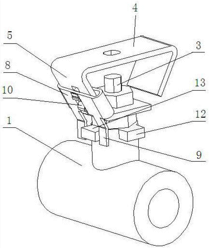
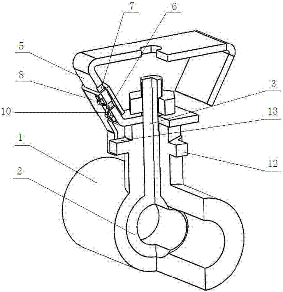
[0024] figure 1 It is a structural schematic diagram of the self-locking ball valve device in one embodiment of the present invention. figure 2 It is a three-dimensional sectional view of the self-locking ball valve device of the present invention in one embodiment. image 3 It is a cross-sectional view of the self-locking ball valve device of the present invention in one embodiment.

[0025] Such as figure 1 , figure 2 and image 3 As shown, the self-locking ball valve device of the present invention includes a valve body 1 , a valve core 2 , and a valve stem 3 connected to the valve core 2 . In addition, in this embodiment, the self-locking ball valve device of the present invention also ...


PUM


Abstract

The invention discloses a self-locking type ball valve device. The self-locking type ball valve device comprises a valve body, a valve element and a valve rod connected with the valve element and further comprises an opening and closing handle, a lock plate, a spring plate and a first locking block, wherein a first limiting groove and a second limiting groove are formed in the vertical part of theopening and closing handle; the lock plate can slide upwards and downwards along the vertical part under the action of external force, and the bottom end of the lock plate is provided with a stop arm; the spring plate is provided with a projection part capable of having elastic deformation; at a first locking working station, the projection part is clamped in the first limiting groove, and accordingly, the stop arm is located at the outer side of the first locking block, so that the first locking block stops the opening and closing handle from rotating by using the shaft center of the valve rod as an axis; when the lock plate is pushed upwards by external force, the projection part has elastic deformation and goes out of the first limiting groove, and the lock plate slides upwards along the vertical part until the projection part falls into the second limiting groove; and at an unlocking working station, the stop arm goes away from the outer side of the first locking block, and the opening and closing handle can freely rotate by using the shaft center of the valve rod as the axis.

Description

technical field [0001] The invention relates to a ball valve device, in particular to a ball valve device used for a long tube air respirator. Background technique [0002] As a kind of respiratory protection equipment, air breathing apparatus has been widely used in heavy industry, sewage treatment, petroleum, chemical industry, shipbuilding and other fields, and is used by firefighters and related staff to deal with harsh operations such as fire, leakage of harmful substances, smog, and lack of oxygen. On-site, so as to carry out fire source detection, fire extinguishing, disaster relief, rescue and rescue work. [0003] Long-tube air respirator is a special application of air respirator. Its working principle is: with compressed air as the air supply source, when the cylinder valve is opened, the high-pressure air stored in the cylinder enters the decompression through the cylinder valve. The high-pressure air is decompressed to medium pressure, and the medium-pressure a...

Claims


Application Information

Patent Timeline
Patent Type & Authority Applications(China)
IPC IPC(8): F16K5/06F16K5/08F16K35/02
CPCF16K5/061F16K5/0647F16K5/08F16K35/02
Inventor 张守政黄锦戴本银吕素花
Owner SHANGHAI BAOYA SAFETY EQUIP
Why Eureka
Try Eureka