Gear shaft of reduction gear of new-energy automobile and manufacturing technology for gear shaft

A technology of new energy vehicles and reducers, which is applied to belts/chains/gears, mechanical equipment, transmission parts, etc. It can solve the problems of low internal structure density, large cutting processing volume, poor impact resistance, etc., and achieve production efficiency High, high product mechanical properties, good quality effect

Pending Publication Date: 2018-05-08
江苏威鹰机械有限公司
View PDF10 Cites 4 Cited by
  • Summary
  • Abstract
  • Description
  • Claims
  • Application Information

AI Technical Summary

Problems solved by technology

The production process of the existing technology has a large amount of cutting and processing, hobbing to form the tooth surface, long production cycle, low efficiency, high cost, cut off metal flow line, low internal structure density, low tooth surface strength, and poor impact resistance

Method used


Image

  • Gear shaft of reduction gear of new-energy automobile and manufacturing technology for gear shaft
  • Gear shaft of reduction gear of new-energy automobile and manufacturing technology for gear shaft
  • Gear shaft of reduction gear of new-energy automobile and manufacturing technology for gear shaft

Examples


Embodiment

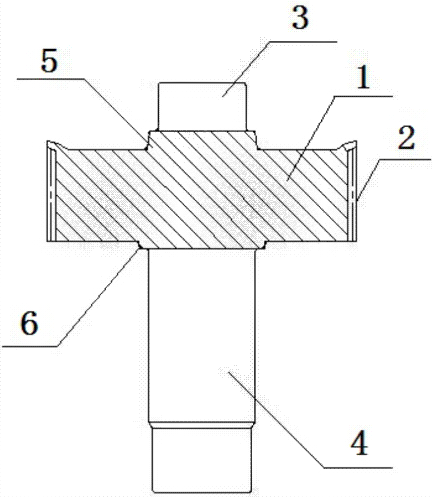
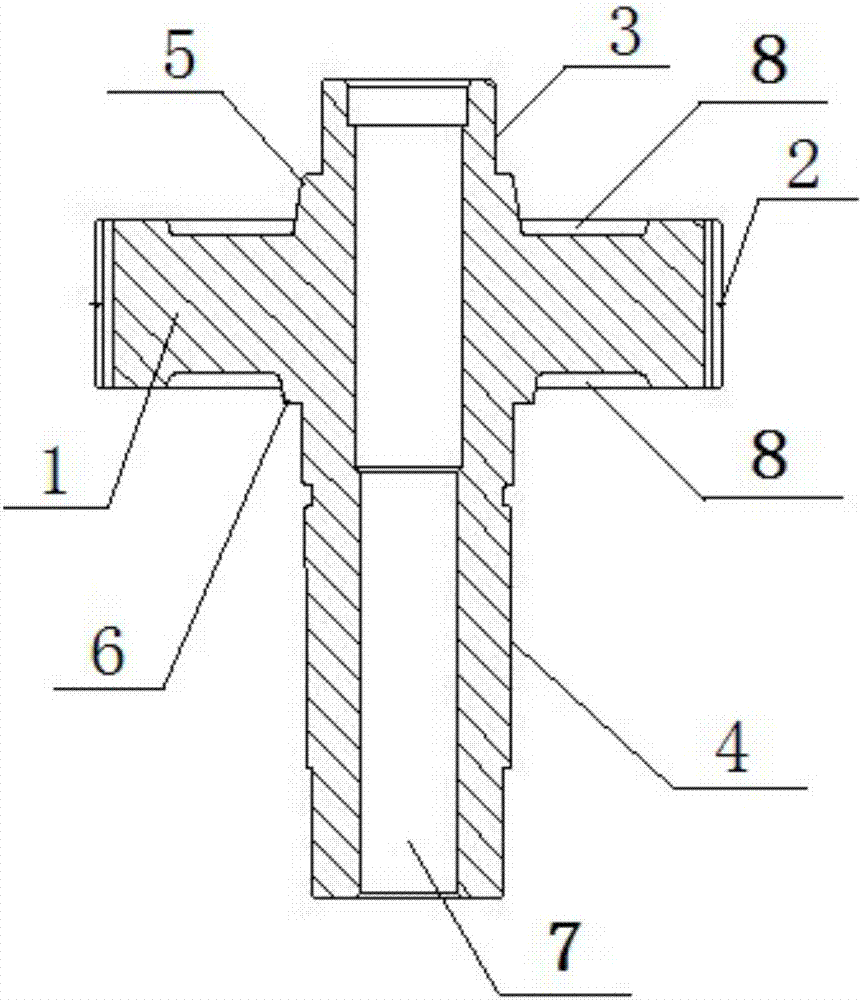
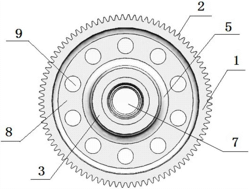
[0021] Example: see figure 1 , figure 2 and image 3 As shown, a new energy vehicle reducer gear shaft includes a rod part and a disc part 1. The disc part 1 is a cylindrical structure and the outer wall is provided with a toothed structure 2. The rod part is vertically arranged at the center of the disc part and divided into upper Rod 3 and lower rod 4, upper transition section 5 and lower transition section 6 are respectively arranged between the upper rod 3 and the lower rod 4 of the disk part and the rod part, and the diameters of the upper and lower transition sections 5 and 6 are respectively larger than the upper rod 3 , the diameter of the lower rod 4, the lower rod 4 is a circular platform structure with a decreasing trend in diameter from the plate to the bottom. A central through hole 7 is formed in the center of the disc portion 1, a groove ring 8 is formed on the upper and lower end surfaces of the disk part 1, and ten weight-reducing holes 9 are uniformly dist...


PUM

PropertyMeasurementUnit
Surface hardnessaaaaaaaaaa

Abstract

The invention discloses a gear shaft of a reduction gear of a new-energy automobile. The gear shaft comprises a rod part and a disc part; the disc part is of a cylindrical structure; a tooth profile structure is arranged on the outer wall of the disc part; the rod part is vertically arranged at the center of the disc part and is divided into an upper rod and a lower rod; and the rod part and the disc part are of an integrated structure formed by forging metal. The invention further discloses a manufacturing technology for the gear shaft. The manufacturing technology comprises the steps that carrying out warm forging forming to form the required shape, then carrying out cold finish forging to form the tooth profile structure, and finally carrying out cutting machining to manufacture a terminal product. According to the gear shaft and the manufacturing technology thereof, traditional cutting gear machining is replaced, the production efficiency is high, raw materials can be saved, and the production cost can be lowered; and meanwhile, the product precision is high, the extrusion forming metal flow line cannot be cut off, the grain structure is compact, the strength of the tooth surface can be improved, the mechanical property of the product is high, and the quality is good.

Description

technical field [0001] The invention relates to an output shaft of a reducer, in particular to a manufacturing process for a gear shaft of a reducer for a new energy vehicle with a large diameter reduction ratio. Background technique [0002] The output shaft of the reducer is an extremely important part inside the reducer. The output shaft is the shaft that outputs power and is an important part of power transmission. At present, in the design of the output shaft of the reducer, the technology is not perfect, and the installation is difficult. Power transmission Instability is most likely to occur. The State Intellectual Property Office discloses a new type of reducer output shaft (CN104179789A). The main body is composed of a fixed seat and a shaft core. , the shaft core is arranged vertically at the center of the fixing seat, and the shaft core is set in a truncated circular shape with a cross-sectional diameter at the top and a cross-sectional diameter at the lower end....

Claims


Application Information

Patent Timeline
IPC IPC(8): F16H57/00B23P15/00
CPCF16H57/0018B23P15/00
Inventor 张太良万永福张华文
Owner 江苏威鹰机械有限公司
Why Eureka
Try Eureka