
Shot blasting machine

A shot blasting machine and shot blasting machine technology, which is applied in abrasive jet machine tools, abrasives, metal processing equipment, etc., can solve the problem of the reduction of the scope of application of the shot blasting machine, and achieve the effects of simple structure, convenient operation and wide application range.

Inactive Publication Date: 2018-05-08
重庆市铭鼎机械制造有限公司
View PDF6 Cites 0 Cited by
  • Summary
  • Abstract
  • Description
  • Claims
  • Application Information

AI Technical Summary

Problems solved by technology

[0006] The purpose of the present invention is to provide a shot blasting machine to solve the problem that the scope of application of the shot blasting machine becomes smaller

Method used


Image

  • Shot blasting machine
  • Shot blasting machine

Examples


Embodiment 1

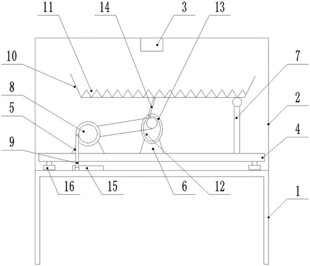
[0020] Such as figure 1 As shown, the shot blasting machine includes a machine base 1, the upper surface of the machine base 1 is welded with a box body 2, and the top of the box body 2 is connected with a shot blasting device 3 through bolts, and the shot blasting machine 3 is located in the middle of the top of the box body 2 , the lower surface of the bottom plate 4 is equipped with a pulley; the left end of the bottom plate 4 is connected with a servo motor 5 by bolts, the middle of the bottom plate 4 is connected with a support seat 6 by bolts, and a cam 12 with a pulley is installed on the support seat 6, and the cam 12 is along the circumference A chute 13 is provided in the direction, and one end of the guide rod 14 is connected with the chute 13 through a runner, and the other end is fixedly connected with the middle position at the bottom of the tray 10, and the upper surface of the tray 10 has evenly distributed V-shaped grooves 11; The right end of the bottom plate...

Embodiment 2

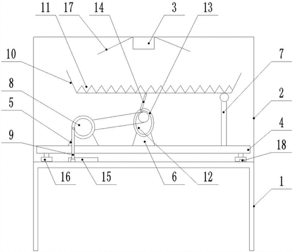
[0023] Such as figure 2 As shown, on the basis of Embodiment 1, inclined baffles 17 are welded on both sides of the blasting device 3, so that the blasting device 3 only blasts the part of the tray 10 to improve the blasting efficiency; The bottom of the groove 11 is provided with a waste chip discharge through hole, which is convenient for the waste chips generated during shot blasting to be discharged through the through hole in time to prevent the waste chips from accumulating in the V-shaped groove 11 and affecting the shot blasting of the parts; before and after the machine base 1 Weld stoppers 18 at both ends to prevent the base plate 4 from slipping out from the slide rail.


PUM


Abstract

The invention belongs to the technical field of polishing equipment and particularly discloses a shot blasting machine. The shot blasting machine comprises a machine seat. A box is arranged on the machine seat. The top of the box is provided with a blast wheel conducting shot blasting towards the inner portion of the box. The upper surface of the machine seat is provided with a base plate connected with the machine seat in a sliding manner. A servo motor is arranged at one end of the base plate. A supporting seat is arranged in the middle of the base plate, and a supporting rod is arranged atthe other end of the base plate. An output shaft of the servo motor is provided with a rotating disk. A telescopic rod is hinged to the rotating disk. A material tray is hinged to the upper end of thesupporting rod. The material tray is provided with V-shaped grooves. A cam is arranged on the supporting seat and provided with a sliding groove in the circumferential direction. A guide rod is hinged to the material tray. The end, opposite to the servo motor, of the machine seat is provided with a spiral guide rail. The telescopic rod is connected with the spiral guide rail in a sliding manner.The shot blasting machine is mainly used for conducting shot blasting on parts and solves the problem that the application range of a shot blasting machine becomes narrow.

Description

technical field [0001] The invention belongs to the technical field of polishing equipment, and specifically discloses a shot blasting machine. Background technique [0002] Shot blasting is a cold treatment process, which is divided into shot blasting cleaning and shot blasting strengthening. Shot blasting can remove impurities such as scale on the surface of metal parts. The metal parts treated by shot blasting improve the appearance quality. Metal parts can improve the fatigue fracture resistance of parts, prevent fatigue failure, plastic deformation and brittle fracture, and improve fatigue life. [0003] At present, the rust and other impurities on the surface of the steel bar are usually treated with a shot blasting machine. Since the steel bar usually has a long length, it is easy to tangle during the treatment process, and the entangled steel bar takes a long time To deal with, and the problem of insufficient throwing is prone to occur during the throwing process. ...

Claims


Application Information

Patent Timeline
Patent Type & Authority Applications(China)
IPC IPC(8): B24C1/10B24C3/00
CPCB24C1/10B24C3/00
Inventor 张序
Owner 重庆市铭鼎机械制造有限公司
Learn More