A safe and reliable bending machine

A bending machine and reliable technology, applied in the field of bending machines, can solve the problems of destroying the accuracy of sheet processing, reducing the qualified rate of workpiece processing, sheet displacement, etc., so as to achieve firm and reliable clamping work, improve the qualification rate, and ensure clamping effect of action

Active Publication Date: 2019-04-16
JIANGSU MINGYU NEW ENERGY RESOURCES
View PDF5 Cites 0 Cited by
  • Summary
  • Abstract
  • Description
  • Claims
  • Application Information

AI Technical Summary

Problems solved by technology

[0003] In the process of bending the sheet, the staff generally needs to manually support the sheet, and when bending one end of the sheet, in order to cooperate with the bending work, the other end of the sheet needs to approach the machine body, At this time, the staff who support the sheet will come into contact with the working body, causing potential safety hazards. At the same time, because the sheet is only bent and processed by the simple support of the staff, for larger areas When the sheet is being bent, it is easy to be unstable and cause the sheet to shift. At this time, the accuracy of the sheet processing will be destroyed and the pass rate of the workpiece processing will be reduced.

Method used


Image

  • A safe and reliable bending machine
  • A safe and reliable bending machine

Examples


Embodiment

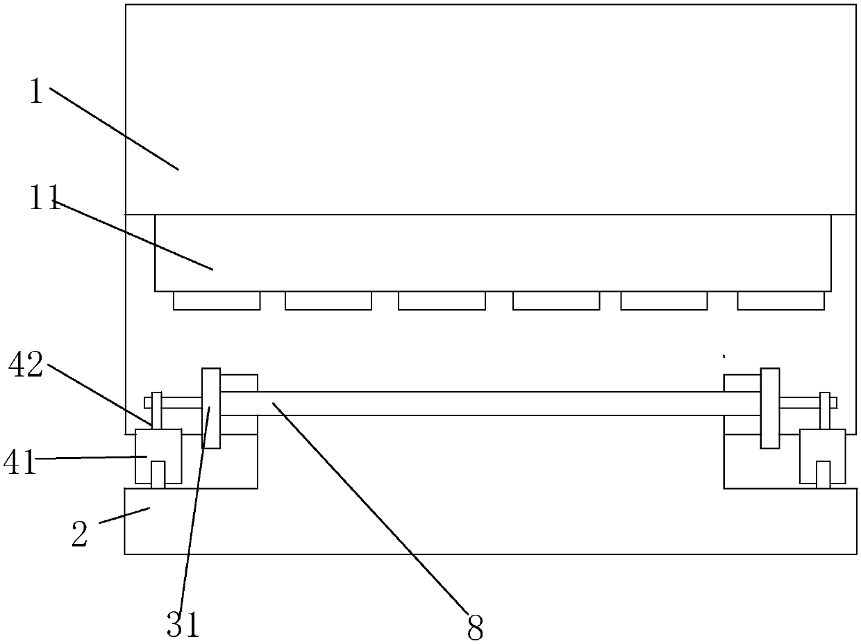
[0022] Embodiment: A safe and reliable bending machine, including a machine body 1, a bending work area 11 arranged on the machine body 1, and a power source (not shown in the figure) that controls the bending work area 11 for bending processing. The part of the workpiece 8 to be bent is placed in the bending work area 11 , and the power source controls the work of the bending work area 11 to realize the bending process of the workpiece 8 .

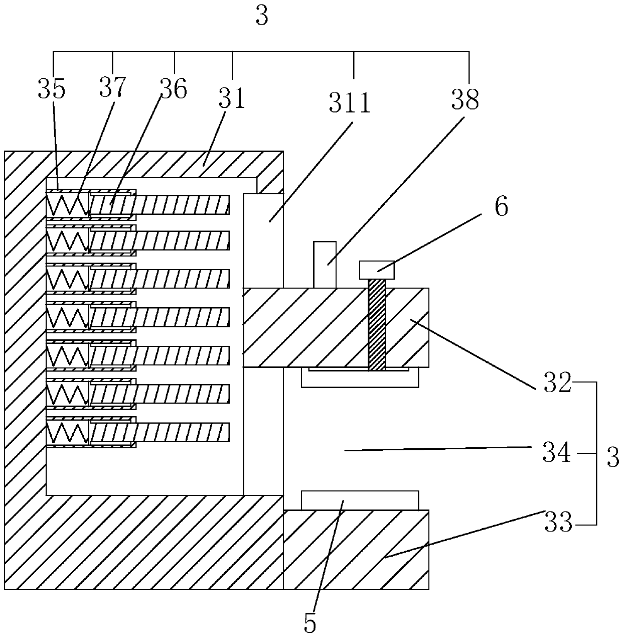
[0023] At this time, a workbench 2 for placing the workpiece 8 is provided on the body 1 close to the bending work area 11. A pair of clamping devices 3 for clamping the workpiece 8 are symmetrically provided at both ends of the workbench 2. The clamping device 3 It includes a connecting plate 31 arranged at one end of the workbench 2, a lower splint 33 and an upper splint 32 are provided on the side of the connecting plate 31 close to the workbench 2, and a working space for inserting the workpiece 8 is formed between the upper splint 32 ...

specific Embodiment approach

[0026] Specific implementation method: Place the sheet workpiece 8 on the workbench 2, and insert the two ends of the workpiece 8 into the working groove 34 of the clamping device 3, so that the workpiece 8 is in conflict with the lower splint 33, and then slide the upper splint 32, to make it slide near the workpiece 8, and conflict with the sheet workpiece 8, and then control the electromagnet 38 to be energized. The upper surface of the upper clamping plate 32 is in contact, so as to realize the impact on the upper clamping plate 32, so that the upper clamping plate 32 is fixed at this position.

[0027] At this time, the clamping work of the upper splint 32 and the lower splint 33 to the sheet workpiece 8 is ensured. During the bending process of the workpiece 8, the hydraulic cylinder 41 works at the same time, and the telescopic movement of the piston rod 42 can drive the clamping device. 3's lifting work, it can also drive the lifting of the sheet workpiece 8, so that t...


PUM


Abstract

The invention discloses a safe and reliable bending machine. The safe and reliable bending machine comprises a machine body and a bending working area, a workbench is arranged at the position, close to the bending working area, of the machine body, and the workbench is symmetrically provided with a pair of clamping devices. Each clamping device comprises a connecting plate which is arranged at oneend of the workbench, wherein an upper clamping plate and a lower clamping plate are arranged at the positions, close to one side face of the workbench, of the connecting plate; a working groove usedfor inserting a workpiece is formed between the upper clamping plate and the lower clamping plate; a rail groove used for sliding and buckled insertion of the upper clamping plate is formed in the connecting plate; a plurality of connecting sleeves are fixedly arranged in the connecting plate in array in the length direction of the rail groove; telescopic rods are arranged in the connecting sleeves in a sliding manner; the ends, located in the connecting sleeves, of the telescopic rods are connected and fixed with the connecting sleeves through connecting springs; the upper surface of the upper clamping plate is fixedly provided with electromagnets for attracting the telescopic rods; and driving mechanisms driving the clamping devices to ascend and descend are arranged at the two ends ofthe workbench. The bending machine can realize clamping work of the workpieces, improves safety, and has high clamping stability, and the yield is improved.

Description

technical field [0001] The invention relates to the field of workpiece processing equipment, in particular to a safe and reliable bending machine. Background technique [0002] The bending machine is a machine capable of bending thin plates. Its structure mainly includes a bracket, a workbench and a clamping plate. The workbench is placed on the bracket. The workbench is composed of a base and a pressure plate. The base is composed of a seat shell, a coil and a cover plate, the coil is placed in the depression of the seat shell, and the top of the depression is covered with a cover plate. When in use, the wire is energized to the coil, and after energization, an attractive force is generated on the pressure plate, so as to realize the clamping of the thin plate between the pressure plate and the base. Due to the use of electromagnetic force clamping, the pressure plate can be made into a variety of workpiece requirements, and the workpiece with side walls can be processed, ...

Claims


Application Information

Patent Timeline
Patent Type & Authority Patents(China)
IPC IPC(8): B21D5/00B21D43/00B21D55/00
CPCB21D5/002B21D55/00
Inventor 徐如兄
Owner JIANGSU MINGYU NEW ENERGY RESOURCES
Why Eureka
Try Eureka