
Wind power main shaft provided with strengthening layer and machining technology of wind power main shaft

A wind power main shaft and processing technology technology, applied in the directions of shafts, bearings, shafts and bearings, etc., can solve the problems of increasing the shaft diameter of the fan main shaft, difficult forging process of the crankshaft, and radial runout of the main shaft, so as to reduce the weight and improve the strength of the main shaft. , the effect of reducing the size of the structure

Pending Publication Date: 2018-05-04
JIANGYIN ZENKUNG FORGING CO LTD
View PDF6 Cites 1 Cited by
  • Summary
  • Abstract
  • Description
  • Claims
  • Application Information

AI Technical Summary

Problems solved by technology

[0003] At present, the diameter of the wind rotor of the wind turbine is getting bigger and bigger, and the weight is also increasing, which causes the size of the connecting flange adjacent to the fan hub on the fan shaft to increase, and the shaft diameter of the fan shaft also increases accordingly. In addition, as people pay more and more attention to the local Hertz contact stress of main shaft bearings, the main shaft bearings of wind turbines tend to choose multi-row single bearings with larger inner diameters. , which results in a complex structure in which the diameters of the fan main bearing connecting flange and the bearing mounting ring are large, and the diameters between the connecting flange and the bearing mounting ring and on both sides are small
The wind power main shaft with this structure is difficult to realize by using the crankshaft forging process. At the same time, because the alloy steel is difficult to process, there are many problems in the method of forging the wind power main shaft as a whole and then processing it. Although a split wind power main shaft has appeared, the two Segmented spindles will experience more severe runout

Method used


Image

  • Wind power main shaft provided with strengthening layer and machining technology of wind power main shaft
  • Wind power main shaft provided with strengthening layer and machining technology of wind power main shaft
  • Wind power main shaft provided with strengthening layer and machining technology of wind power main shaft

Examples


Embodiment Construction

[0034]The specific implementation manners of the present invention will be further described below in conjunction with the drawings and examples. The following examples are only used to illustrate the technical solution of the present invention more clearly, but not to limit the protection scope of the present invention.

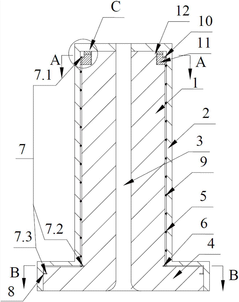
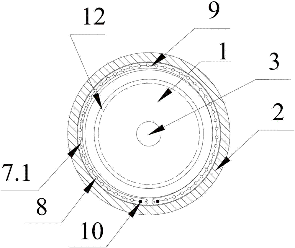
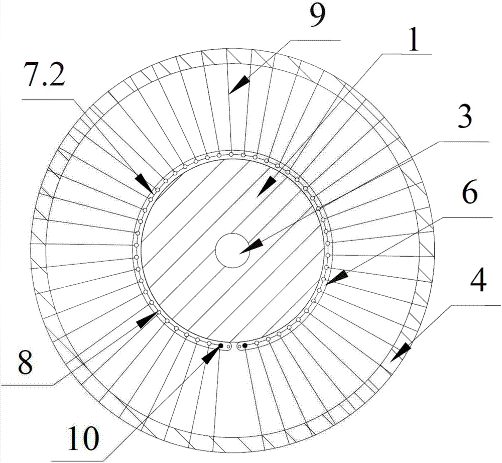
[0035] Such as Figure 1~5 As shown, the present invention is a wind power main shaft provided with a reinforcement layer. The wind power main shaft includes a mandrel 1 and a sleeve shaft 2, and a carbon fiber mold sleeve layer or a carbon fiber mesh layer is arranged between the mandrel 1 and the sleeve shaft 2. The wind power main shaft is provided with an axial center hole 3 , and one end of the wind power main shaft is provided with a flange 4 .

[0036] In order to facilitate the clamping of carbon fiber filaments or carbon fiber membranes inside the wind power main shaft so that it forms an integral structure with the wind power main shaft, a preferr...


PUM


Abstract

The invention discloses a wind power main shaft provided with a strengthening layer. The wind power main shaft comprises a core shaft and a sleeve shaft; a carbon fiber die sleeve layer or a carbon fiber mesh layer is arranged between the core shaft and the sleeve shaft; the wind power main shaft is provided with an axial center hole; and a flange plate is arranged at one end of the wind power main shaft. A machining technology of the wind power main shaft comprises the steps that the core shaft and the sleeve shaft are machined according to designed sizes, an axial groove or a spiral groove into which a carbon fiber is inserted and a spring expansion ring for being embedded into an annular groove are machined in the surface of the core shaft, a threading hole through which the carbon fiber is penetrated is machined in the spring expansion ring, the carbon fiber embedded into the groove generates pretightening force through an adjusting nut, the core shaft embedded with the carbon fiber is put in a refrigeration warehouse for refrigeration, the sleeve shaft is put in a heating furnace for heating, the refrigerated core shaft and the heated sleeve shaft are arranged in a sleeving manner, and after the sleeved wind power main shaft reaches the normal temperature, the wind power main shaft can be used for subsequent machining. With the adoption of the structure and the machining technology, the structural size of the wind power main shaft of a wind power generator can be reduced substantially, and the strength of the wind power main shaft can be improved.

Description

technical field [0001] The invention relates to the field of machining technology for a main shaft in a wind power generator, in particular to a wind power main shaft provided with a reinforcement layer and a machining process thereof. Background technique [0002] In recent years, due to the continuous shortage of natural resources, people have become more and more active in the development and utilization of new energy, especially clean energy. Among them, wind power is clean and environmentally friendly, renewable, non-polluting, large in energy, and has broad prospects. , has become a strategic choice for countries all over the world. [0003] At present, the diameter of the wind rotor of the wind turbine is getting bigger and bigger, and the weight is also increasing, which causes the size of the connecting flange adjacent to the fan hub on the fan shaft to increase, and the shaft diameter of the fan shaft also increases accordingly. In addition, as people pay more and...

Claims


Application Information

Patent Timeline
IPC IPC(8): F16C3/02B23P15/14
CPCF16C3/023B23P15/14F16C2202/06F16C2360/31F16C2361/31F16C2206/02F16C2223/00Y02E10/72
Inventor 兰驹赵建兴戚振华杨春
Owner JIANGYIN ZENKUNG FORGING CO LTD
Learn More