
Small structured light illumination super-resolution microscopic imaging system

A technology of structured light illumination and microscopic imaging, which is applied in microscopes, optics, optical components, etc., can solve the problems of complex optical path, bulky volume, and low cost, and achieve the effect of compact system structure, small volume, and cost reduction

Active Publication Date: 2018-04-27
INST OF SEMICONDUCTORS - CHINESE ACAD OF SCI
View PDF4 Cites 8 Cited by
  • Summary
  • Abstract
  • Description
  • Claims
  • Application Information

AI Technical Summary

Problems solved by technology

However, these algorithms still use the above-mentioned structured light illumination imaging system based on spatial light modulators experimentally, and there is no system dedicated to this algorithm at present
[0007] In summary, the current mainstream structured light illumination super-resolution imaging system has a complex and long optical path, and the overall system is bulky. Although a small-volume system has been proposed, it still relies on the high-cost spatial light modulator, and only Able to realize lighting function
At present, there is no structured light illumination super-resolution microscopy imaging system with simple structure, low cost, and integrated illumination and imaging.

Method used


Image

  • Small structured light illumination super-resolution microscopic imaging system
  • Small structured light illumination super-resolution microscopic imaging system
  • Small structured light illumination super-resolution microscopic imaging system

Examples


Embodiment 1

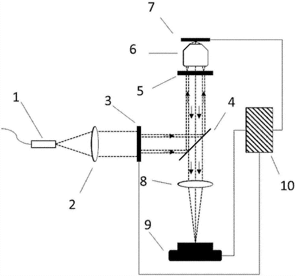
[0033] like figure 2 As shown, a small structured light illumination super-resolution microscopy imaging system includes a light source 1, a collimator lens 2, a rotating light barrier module 3, a dichroic mirror 4, a filter plate 5, a microscope objective lens 6, and an object stage 7 , imaging lens 8, photodetector 9 and synchronous control system 10, collimator lens 2 placed behind light source 1, rotating light barrier module 3 placed behind collimating lens 2, dichroic mirror 4 placed in rotating barrier module 3 Finally, at an angle of 45 degrees, the filter plate 5, the microscope objective lens 6, and the stage 7 are placed above the dichroic mirror 4 in turn, and the imaging lens 8 and photodetector 9 are placed below the dichroic mirror 4 in turn. The filter plate 5 is placed on the entrance pupil plane of the microscope objective lens 6 (ie, the rear focal plane); the synchronous control system 10 connects the rotating light barrier module 3, the stage 7 and the ph...


PUM


Abstract

The invention discloses a small structured light illumination super-resolution microscopic imaging system which includes a laser light source, a collimating lens, a rotary light baffle module, a dichroic mirror, a filter plate, a microscopic objective lens, a carrier table, an imaging lens, a photoelectric detector and a synchronous control system. The light emitted by the laser light source is collimated by the collimating lens into parallel beams, the parallel beams are partially blocked by the rotary light baffle module, divided by the dichroic sheet and filtered by the filter plate placedon the entrance pupil surface of the microscopic objective lens, and then, structured light illumination is formed on the surface of a sample on the carrier table through the microscopic objective lens. The imaging lens and the photoelectric detector are placed behind the dichroic mirror and used for forming an image of fluorescence distribution on the surface of the sample. The synchronous control system is connected in a control manner with the rotary light baffle module, the carrier table and the photoelectric detector. The small structured light illumination super-resolution microscopic imaging system has the advantages of small size, compact structure, low cost, and the like, and is easy to carry. The application scope of structured light illumination super-resolution imaging is greatly extended.

Description

technical field [0001] The invention relates to a super-resolution microscopic imaging system, in particular to a small structured light illumination super-resolution microscopic imaging system. Background technique [0002] Due to the limitation of the optical diffraction limit, the traditional optical microscope has a lateral limit resolution of 200nm and a vertical limit resolution of about 500nm for visible light band imaging, which cannot meet the needs of current life science research for the observation of subcellular structures and other micro-scale structures. [0003] Structured light illumination super-resolution imaging technology was first proposed by Neil et al. in 1997. This technology uses non-uniform structured light to illuminate the sample, and through the corresponding image reconstruction algorithm, achieves super-resolution imaging that breaks through the optical diffraction limit. Its resolution is relatively high. The traditional optical microscope is...

Claims


Application Information

Patent Timeline
Patent Type & Authority Applications(China)
IPC IPC(8): G02B27/58G02B21/06
CPCG02B21/06G02B27/58
Inventor 胡诗铭黄义征刘文文魏清泉俞育德
Owner INST OF SEMICONDUCTORS - CHINESE ACAD OF SCI
Learn More