Liquid fuel cutting torch control valve and automatic-cutting cutting torch

An automatic cutting and liquid fuel technology, applied in valve details, multi-way valves, valve devices, etc., can solve the problems of large waste, tempering and flashing, and the inability to realize standardization and automation, etc., to achieve precise control and sufficient fuel combustion Effect

Pending Publication Date: 2018-04-27
烟台蓝焰杰能焊割设备有限公司
View PDF6 Cites 0 Cited by
  • Summary
  • Abstract
  • Description
  • Claims
  • Application Information

AI Technical Summary

Problems solved by technology

[0004] During the use of the known gas or liquid fuel welding and cutting torch, it is necessary to rely on operating experience to repeatedly adjust the three channel adjustment knobs, which cannot achieve standardization and automation. Especially in the operation of liquid fuel instead of gas fuel welding and cutting torch, the adjustment is more difficult Large, which greatly limits the promotion and use of liquid fuel energy-saving welding and cutting torches, and cannot meet the requirements of automatic welding and cutting equipment using liquid fuel
[0005] In addition, the known liquid fuel welding and cutting torches all directly suck out the liquid fuel by the injection pipe, and send it to the welding and cutting nozzle for combustion through the torch head along with the preheated oxygen and high-pressure air. Most of its mixed oxygen channels are single-hole or double-hole, and are located on the side of the hand, without atomization function
On the one hand, the fuel is in the state of a large amount of liquid flow, the combustion is very insufficient, and the waste is huge; on the other hand, the combustion process is unstable, with serious flashback and partial burning, which is not safe, and the cutting nozzle is easy to burn; long-term constraints Development and industrial application of liquid fuel welding and cutting torch
[0006] In some technical solutions, metal atomizers with wire mesh and / or asbestos atomizers are added to the oil outlet end of the oil pipeline. Although they can play the role of atomizing liquid fuel, the materials of these filtering devices are fine Silk fibers are used in agglomerates, and there are problems such as airflow scouring, deformation of the screen and easy blockage. The state is unstable, and in fact, it cannot run stably for a long time.

Method used


Image

  • Liquid fuel cutting torch control valve and automatic-cutting cutting torch
  • Liquid fuel cutting torch control valve and automatic-cutting cutting torch
  • Liquid fuel cutting torch control valve and automatic-cutting cutting torch

Examples


Embodiment 1

[0087] Figure 19 Some process holes are drawn in the middle, such as the second gun head mixed oxygen channel 4-6 and the second gun head hyperbaric oxygen channel 4-5, both of which are right-angle bent channels and also include two passages, which need to be connected to the body To start perforating the outer wall of the device, the formation of each channel must leave a process hole on the outer wall of the connecting body, and these process holes need to be blocked later.

[0088] Such as Figure 1-Figure 19 As shown,

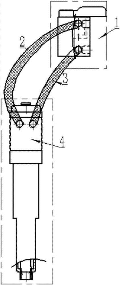
[0089] An automatic cutting torch, comprising the above-mentioned control valve 1 and a cutting unit 4, the cutting unit 4 and the control valve 1 are connected through a hyperbaric oxygen pipe 2 and a mixed oxygen pipe 3, the hyperbaric oxygen pipe 2 and the The mixed oxygen pipes 3 are all hoses; the second valve body hyperbaric oxygen channels 1-14 and the valve body mixed oxygen channels 1-17 are respectively connected to the cutting unit 4 through the hyp...

Embodiment 2

[0102] The difference from embodiment 1 lies in: Picture 20 As shown, the hyperbaric oxygen interface 4-1 and the mixed oxygen interface 4-2 are axially consistent, and the hyperbaric oxygen interface 4-1 and the mixed oxygen interface 4-2 are axially consistent with the connecting body. , The second torch head hyperbaric oxygen passage 4-6 and the second torch head mixed oxygen passage 4-5 are both bent channels, and the axial direction of the mixed oxygen flow regulating valve is the same as that of the torch head body The axis is vertical.

[0103] The working principle of the present invention is as follows:

[0104] Rotate the valve stem 1-2 to Figure 8-10 When shown, the marbles in the first high-pressure oxygen passage, the first valve body preheating oxygen passage, and the first valve body fuel passage are not pushed open, and the high pressure oxygen, preheating oxygen and fuel cannot pass through. At this time, the cutting torch Is closed.

[0105] Rotate the valve ste...


PUM


Abstract

The invention relates to a liquid fuel cutting torch control valve. The liquid fuel cutting torch control valve comprises a valve body and a valve rod, and is further equipped with a two-valve-body high-pressure oxygen channel, a second valve body pre-heating oxygen channel, a second valve body fuel channel and a valve body mixed oxygen channel, wherein a valve body through hole is formed in the valve body; the valve rod can rotatably pass through the valve body through hole; a valve body oxygen gas inlet and a first valve body fuel channel are arranged on the valve body; the valve body oxygengas inlet communicates with a first valve body high-pressure oxygen channel and an inlet of a first valve body pre-heating oxygen channel; and a marble assembly for controlling each of the first valve body high-pressure oxygen channel, the first valve body pre-heating oxygen channel and the first valve body fuel channel to open and close is arranged in each of the first valve body high-pressure oxygen channel, the first valve body pre-heating oxygen channel and the first valve body fuel channel. The invention further relates to an automatic-cutting cutting torch which comprises the control valve and a cutting unit, wherein the cutting unit and the control valve are connected through a high-pressure oxygen tube and a mixing oxygen tube; both of the high-pressure oxygen tube and the mixingoxygen tube are hoses; and the control valve can realize one-valve control of three functions of closing, igniting and welding-cutting.

Description

Technical field [0001] The invention relates to a cutting torch control valve and an automatic cutting torch, in particular to a liquid fuel cutting torch control valve and an automatic cutting torch. Background technique [0002] Flame welding and cutting widely use acetylene, propane, natural gas and other gas fuels, which consumes a lot of energy and costs. In comparison, liquid fuels such as gasoline, diesel, and methanol are used in flames, with low oxygen consumption, low fuel costs, better safety, and overall cost savings of more than 30-80%, which is the development direction of flame welding. [0003] At present, the known gas or liquid fuel welding and cutting torches are all operated with three channel adjustment knobs for oxygen, fuel (gas or liquid), and mixed gas, and lack a control valve that can realize one-key operation. [0004] During the use of the known gas or liquid fuel welding torch, it is necessary to repeatedly adjust the three channel adjustment knobs depe...

Claims


Application Information

Patent Timeline
IPC IPC(8): B23K7/00B23K7/10F16K11/044F16K31/60
CPCF16K11/044F16K31/60B23K7/00B23K7/10
Inventor 孙京钢
Owner 烟台蓝焰杰能焊割设备有限公司
Why Eureka
Try Eureka