
Triangular cable with optical fiber

An optical cable and triangular technology, applied in the field of triangular cables, can solve the problems of troublesome use and maintenance, short circuit of cables, shortened service life of cables, etc., and achieve the effect of saving filling materials and wrapping tapes, reducing material waste, and convenient use and maintenance.

Inactive Publication Date: 2018-04-20
WUXI JIANGNAN CABLE
View PDF6 Cites 0 Cited by
  • Summary
  • Abstract
  • Description
  • Claims
  • Application Information

AI Technical Summary

Problems solved by technology

[0003] In the prior art, the outer diameter of the circular structure cable is large, and it is laid in the wire slot, especially when multiple cables are required to be laid overlappingly at the same time, the laying space is still very large, which limits the use in a narrow space; When laying and installing, the cables are easy to be entangled, and the identification is difficult, and the use and maintenance are troublesome; again, it is difficult to identify the circular cable cores, especially two equal-section conductors, which need to be identified for each core; When the cable is shaped, due to its structural characteristics, it is more difficult to make the torsional moment of the entire cable zero. In many occasions, the cable needs to be moved repeatedly, bent, or used vertically. The torsion of the cable itself and the torsion added during manufacturing , and the increased torsion caused by careless installation, especially when used vertically, the lower end of the cable superimposes and bears the torsional force released from the upper part, so the torsional force is the largest, so after several months of use, distortion, bulge, broken skin, and even breakage will occur Wire
These are not only easy to cause accidents, cause short circuit of the cable or damage the equipment; but also shorten the service life of the cable

Method used


Image

  • Triangular cable with optical fiber

Examples


Embodiment Construction

[0012] The present invention will be further described below in conjunction with accompanying drawing.

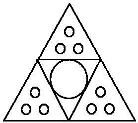
[0013] The structure of the present invention is as figure 1 As shown, the cable includes a triangular optical cable and a triangular structure formed by combining three triangular cores twisted around the optical cable. The triangular optical cable includes an optical cable core and a triangular protective layer covering the optical cable; the triangular wire The core includes several wire cores and an insulating layer covering the wire cores in a triangular shape.

[0014] As a further improvement, the number of said wire cores is one to three.

[0015] Both the wire core and the optical cable core of the present invention are dragged directly, which saves filling materials and wrapping tapes, reduces the material waste of twisting to increase the length, and reduces weight; and there is no entanglement between the wire core and the optical cable core, and the identifica...


PUM


Abstract

The invention provides a triangular cable with an optical fiber. The cable is of a triangular shape and comprises a triangular outer protective sleeve and four triangular cable cores which are stranded in the outer protective sleeve, wherein each cable core comprises a triangular insulating layer and one to three wire cores arranged in the insulating layer. According to the triangular cable provided by the invention, optical cable cores are arranged in the innermost layer; the optical cable cores not only can have an effect similar with steel wire armoring, can have a very good protection effect on the optical cable cores; effectively alleviate damages caused by an external force, but also can have a shielding effect, effectively reduce electromagnetic interference to peripheral electricalequipment and external electromagnetic interference.

Description

technical field [0001] The invention relates to the field of electric wires and cables, in particular to a triangular cable with optical fibers. Background technique [0002] The four-core cable in the prior art generally has a structure in which two extruded circular cores or two fan-shaped cores are twisted. The four-core cable core includes two fourth-class cores with the same conductor cross-section or three 3+1 cores with a large conductor cross-section and one conductor with a small cross-section. The twisting of two circular cores, especially the twisting of two circular cores with unequal cross-sections, has a large gap between the cores, which not only makes the roundness of the cable poor, but also tends to loosen during extrusion and construction, and the wires The core is prone to shifting. For this reason, filler materials are usually added and twisted together. When twisting, the outer layer needs to be tied tightly with tape, and the sheath is squeezed after ...

Claims


Application Information

Patent Timeline
Patent Type & Authority Applications(China)
IPC IPC(8): H01B7/00H01B7/17H01B7/22H01B7/36G02B6/44
CPCH01B7/0009G02B6/443H01B7/17H01B7/225H01B7/36
Inventor 汪磊张传省皇甫富莲
Owner WUXI JIANGNAN CABLE
Learn More