
Forming pressing-fit machine for car brake pad

A brake pad forming and pressing machine technology, which is applied to friction linings, mechanical equipment, gear transmission mechanisms, etc., can solve problems affecting equipment stability, hydraulic column scratches, and reduce the service life of hydraulic columns, etc., to achieve easy installation Fast, easy operation, stable operation effect

Active Publication Date: 2018-04-20
东莞市罗兰制动技术有限公司
View PDF4 Cites 0 Cited by
  • Summary
  • Abstract
  • Description
  • Claims
  • Application Information

AI Technical Summary

Problems solved by technology

[0005] The existing automobile brake pad forming and pressing machine is generally hot-pressed by a four-column hydraulic machine, and the piston rod of the hydraulic column of the four-column hydraulic machine is exposed to the air. There is a certain amount of dust in the factory building. When more and more dust is attached to the hydraulic column On the piston rod, it may cause scratches to the hydraulic column, thereby reducing the service life of the hydraulic column and affecting the stability of the equipment

Method used


Image

  • Forming pressing-fit machine for car brake pad
  • Forming pressing-fit machine for car brake pad
  • Forming pressing-fit machine for car brake pad

Examples


Embodiment Construction

[0022] The following will clearly and completely describe the technical solutions in the embodiments of the present invention with reference to the accompanying drawings in the embodiments of the present invention. Obviously, the described embodiments are only some, not all, embodiments of the present invention. Based on the embodiments of the present invention, all other embodiments obtained by persons of ordinary skill in the art without making creative efforts belong to the protection scope of the present invention.

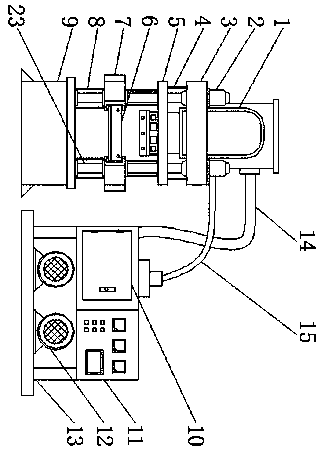
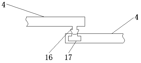
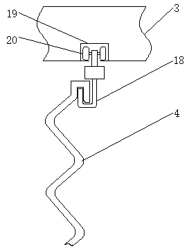
[0023] see Figure 1-6 , the present invention provides a technical solution: a forming and pressing machine for automobile brake pads, comprising a main hydraulic column 1, a main oil pipe 14 is connected to the right side of the main hydraulic column 1, and a fuel tank 10 is connected to the right side of the main oil pipe 14, and the fuel tank 10 The right side is provided with a control cabinet 11, the bottom of the control cabinet 11 is provided with a mo...


PUM


Abstract

The invention relates to a forming pressing-fit machine for a car brake pad. The forming pressing-fit machine comprises a primary hydraulic column. A primary oil pipe is connected to the right side ofthe primary hydraulic column, and an oil tank is connected to the right side of the primary oil pipe. The top of the oil tank is connected with a secondary oil pipe, and the left side of the top of the secondary oil pipe is connected with a secondary hydraulic column. The bottom of the secondary hydraulic column is provided with a piston rod, and a buckle is arranged at the left end of a first dustproof cover. A groove is formed in the right end of the first dustproof cover, and the top end of the first dustproof cover is connected with a hook. The top of the hook is connected with a roller,and a through groove is formed in the outer side of the roller. An upper beam is arranged on the outer side of the through groove, and a baffle is arranged at the bottom of the right end of the through groove. A sliding beam is arranged at the bottom of the first dustproof cover, and the bottom of the sliding beam is connected with a fixing strip and provided with a second dustproof cover. The portions, between the upper beam and the sliding beam, between the sliding beam and a lower beam as well as between the lower beam and a base and exposed to air, of the piston rod can be protected through structures of the first dustproof cover and the second dustproof cover, operating of the forming pressing-fit machine is more stable, and the service life is longer.

Description

technical field [0001] The invention relates to the technical field of brake pad production equipment, in particular to an automobile brake pad forming and pressing machine. Background technique [0002] Brake pads are also called brake pads. In the braking system of a car, the brake pads are the most critical safety parts. The brake pads play a decisive role in the quality of all braking effects, so good brake pads are the protectors of people and cars. [0003] Brake pads are generally composed of steel plates, adhesive insulation layers and friction blocks. The steel plates must be painted to prevent rust. During the painting process, SMT-4 furnace temperature tracker is used to detect the temperature distribution during the painting process to ensure the quality. The heat insulation layer is composed of materials that do not conduct heat, and the purpose is heat insulation. The friction block is composed of friction material and adhesive, which is squeezed on the brake...

Claims


Application Information

Patent Timeline
Patent Type & Authority Applications(China)
IPC IPC(8): B29C51/18B29C51/26F16D69/02
CPCB29C51/18B29C51/26F16D69/02F16D2200/0086F16D2250/0023
Inventor 张国汉
Owner 东莞市罗兰制动技术有限公司
Learn More