
Multi-function tool box with side doors

Inactive Publication Date: 2009-04-02
JIANGSU TONGRUN EQUIP TECH
View PDF23 Cites 18 Cited by
  • Summary
  • Abstract
  • Description
  • Claims
  • Application Information

AI Technical Summary

Benefits of technology

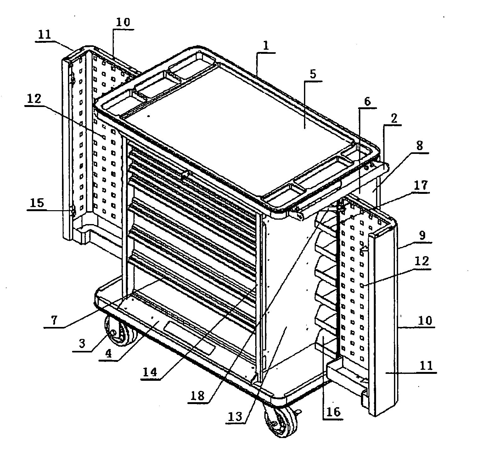
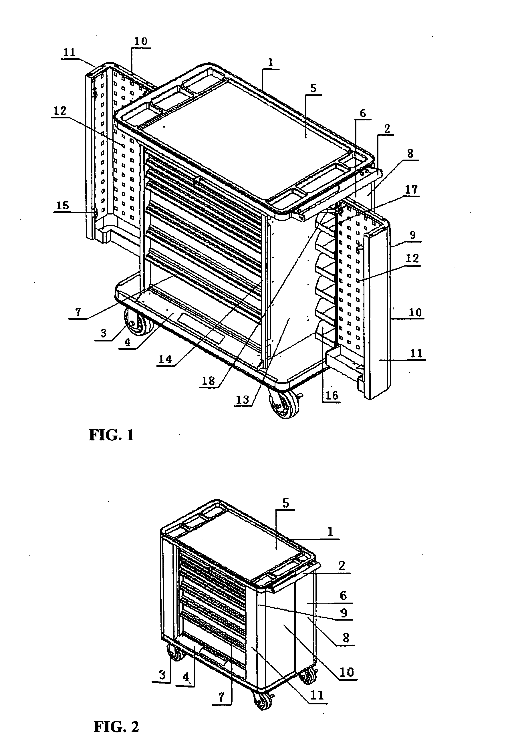
[0005]In the multi-function tool box with side doors of this utility model based on above design, since tool box main body middle part adopts drawer structure, features of traditional tool box are maintained to allow classified storage of various tools. On both sides of box body, side door that can be opened is provided, on internal surface of which hanging plate for various commonly used tools is provided so that user can see and take / put back required tools at a glance. In the left and right available space at rear of box body, a number of part boxes or small drawers for classified storage of various parts and easy taking are provided as required. For operation, said left and right side doors can rotate about hinges outward for opening, and toward middle drawers for closing. In closed status, these doors are integral to box body. Therefore, since in the overall design, actual requirements on operation are fully considered, not only a group of drawers for classified storage of maintenance tools are provided, facilitating hanging of open type hanging plates for commonly used tools, containers for classified spares required for daily maintenance are also provided. Compared with traditional tool box, the new multi-function tool box with side doors features high space availability, large quantity and complete types of tools and spares stored, greatly facilitating site maintenance, and very strong practicality.

Problems solved by technology

In this way, stored commonly used tools are not apparently seen, and it takes time and trouble to locate required tools.
Further more, space dedicated to hardware is not available, not satisfying easy use for site maintenance.

Method used


Image

  • Multi-function tool box with side doors
  • Multi-function tool box with side doors

Examples


embodiment

Preferred Embodiment

[0027]The following further describes this utility model in combination with figures and preferred embodiment.

[0028]In FIG. 1 and FIG. 2, main body of multi-function tool box with side doors of this utility model consists of box body 1 and handle 2, with box body 1 comprising base 4 with foot wheels 3, head plate 5, left / right side boards 6, and a group of drawers 7; characterized by drawers 7 provided in middle part of box body 1 and drawn back at left and right side; left / right side board 6 comprising fixed external side boards 8 provided at rear outer side of box body 1 and main plane 10 of left and right side doors 9 functioning as remaining part of left and right side board; a lateral plate connected to hinge is provided on front edge of fixed external side board 8; main body of left and right side doors 9 (that can be opened) having “L” shape and comprising main plane 10 that can function as remaining part of said left and right side board on box and auxili...


PUM


Abstract

This utility model relates to a type of multi-function tool box with side doors, consisting of a base with foot wheels, head plate, left and right side boards, box body formed by a group of drawers, and handle. Drawers in the box slightly draw back at left and right sides. At rear of the box, fixed left and right side boards are provided. In available space formed between fixed external side boards and left / right drawn back drawer side plates, parts container is provided. At left and right side of drawers in front of this available space, left and right side doors that can be opened and function as part of left / right side board and part of front board of the box. On internal walls of these side doors, tool hanging plates with holes are provided. When these side doors move outward, the tool box is open; when they are withdrawn, an enclosed box is formed. Compared with traditional tool box, space availability is apparently high, quantity of tools and spares that can be stored in this box is large, types of such tools and spares are complete, and taking of these tools and spares is convenient, greatly facilitating site maintenance and service, and providing very strong practicality.

Description

FIELD OF THE INVENTION[0001]This utility model relates to a type of work piece storage device, in particular a type of multi-function tool box with side doors that has large storage space and allows apparent classified storage and easy withdrawal of various tools and hardware.BACKGROUND OF THE INVENTION[0002]In the present market, tool containers are mainly drawer box type, in which tools are kept in drawers or on box partition plates in a mixed manner. In this way, stored commonly used tools are not apparently seen, and it takes time and trouble to locate required tools. Further more, space dedicated to hardware is not available, not satisfying easy use for site maintenance.DETAILED DESCRIPTION[0003]The purpose of this utility model is to provide a new type of multi-function tool box with side doors of reasonable structure, capable of classified storage of maintenance tools, and with dedicated container for hardware.[0004]Main body of multi-function tool box with side doors of this...

Claims


Application Information

Patent Timeline
IPC IPC(8): A47B96/16
CPCB25H3/00
Inventor ZHANG, FENG
Owner JIANGSU TONGRUN EQUIP TECH
Learn More