Infrared hot spot detection device
A detection device, infrared temperature measurement technology, applied in hot spot detection, measurement devices, optical radiation measurement, etc., can solve the problems of high application environment requirements, inaccurate data collection, easy damage, etc., to achieve clean and dry protection, increase monitoring Range, the effect of reducing the damage rate
- Summary
- Abstract
- Description
- Claims
- Application Information
AI Technical Summary
Problems solved by technology
Method used
Image
Examples
specific Embodiment approach 1
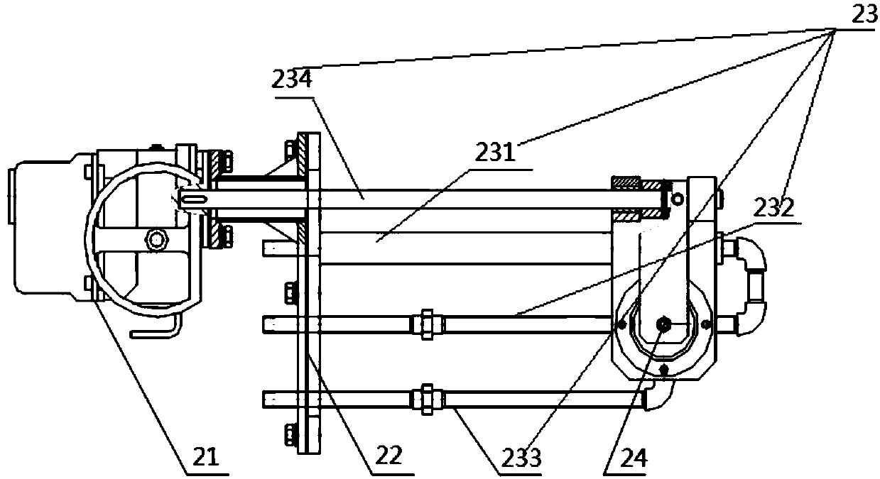
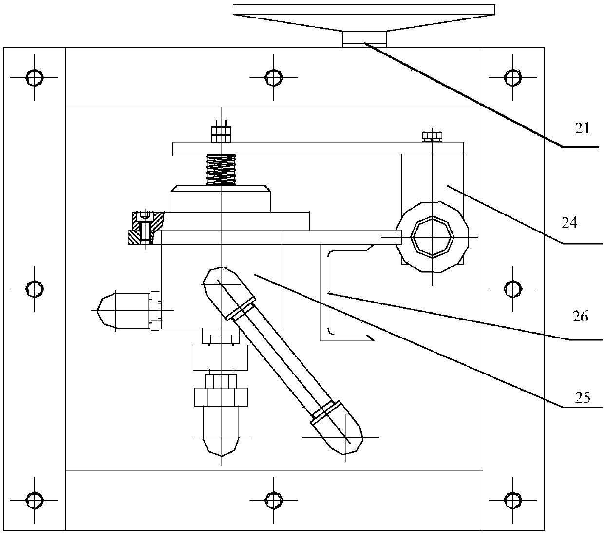
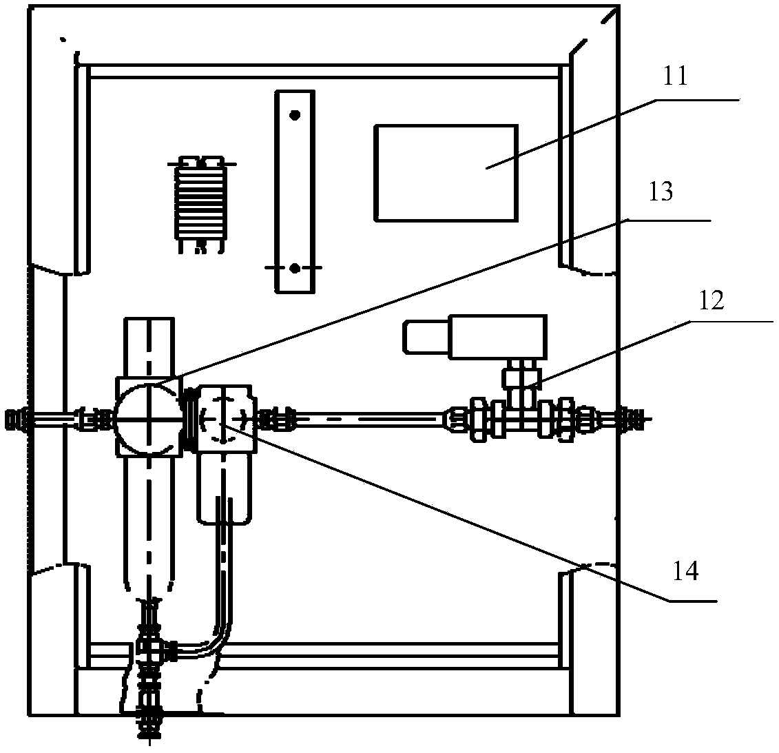
[0034] An infrared hot spot monitoring device, comprising an infrared temperature measuring sensor control cabinet and a sensor fixing mechanism; the infrared temperature measuring sensor control cabinet includes a data collector 11, a cooling air flow switch 12, a filter pressure reducing valve 13 and an oil separator 14, the The sensor fixing mechanism includes an electric actuator 21, a mounting plate 22, a pipeline 23, a protective cover 24, an infrared probe assembly 25, and an optical lens 26; And the second gas pipeline 234, the infrared probe assembly 25 includes at least one infrared temperature sensor; the infrared temperature sensor data line is connected to the terminal of the infrared temperature sensor control cabinet, and the first gas pipeline 233 is connected by a pipeline Cooling air flow switch 12; the electric actuator 21 is connected to the second air pipeline 234 and the protective cover 24, the second air pipeline 234 is connected to the first air pipelin...
specific Embodiment approach 2
[0041] In the infrared hot spot detection device, the infrared probe assembly 25 includes a power module 251 , an input module 252 , an infrared temperature sensor module 253 , a first redundant chip module 254 and a second redundant chip module 255 .
[0042] Such as Figure 4 As shown, the power module 251 includes a power supply U7, model LTC4416, two power field effect transistors Q1 and Q2, model IRF9540, capacitors C3 and C4; V1, G1 and VS terminals of U7 are respectively connected to the drain, gate and source of Q1 The VS, G2 and V2 terminals of U7 are respectively connected to the source, gate and drain of Q2, the V1 and E1 terminals of U7 are connected to 24V1, the GND terminal and E2\ are connected to the ground wire, the V2 terminal is connected to the 24V2 terminal, and the 24V terminals are respectively The capacitor C3 and the capacitor C4 are connected to each other, and the capacitor C3 and the capacitor C4 are respectively connected to the ground wire.
[00...
PUM
 Abstract
Description
Claims
Application Information
 - Generate Ideas
- Intellectual Property
- Life Sciences
- Materials
- Tech Scout
- Unparalleled Data Quality
- Higher Quality Content
- 60% Fewer Hallucinations
Browse by: Latest US Patents, China's latest patents, Technical Efficacy Thesaurus, Application Domain, Technology Topic, Popular Technical Reports.
© 2025 PatSnap. All rights reserved.Legal|Privacy policy|Modern Slavery Act Transparency Statement|Sitemap|About US| Contact US: help@patsnap.com


